Gas-liquid mixed multi-piston disk brake system

A disc brake, gas-liquid mixing technology, applied in the direction of hydraulic brake transmission, etc., can solve the problems of long working time of the brake system, placement of the brake, large structural size, etc., to achieve thermal stability and water wading Good recovery, short braking reaction time and constant braking performance

Inactive Publication Date: 2006-02-08
WUHAN UNIV OF TECH
View PDF0 Cites 1 Cited by
  • Summary
  • Abstract
  • Description
  • Claims
  • Application Information

AI Technical Summary

Problems solved by technology

[0003] Both theory and practice show that because the viscosity of gas is much lower than that of liquid, the gas pressure of the pneumatic system is usually only about 1 / 20 of the liquid pressure in the hydraulic brake system, and when the car is in a non-braking state, the brake control valve to each The entire pipeline system of the brake cylinder and each brake cylinder are in an atmospheric state. Therefore, 1. The brake cylinders of the air pressure brake system are not only large in structure size, but cannot control the braking force like the hydraulic brake system. The dynamic cylinder is placed in the brake (the brake cylinder of the air brake system is all set outside the brake). Moreover, a set of force transmission and force amplification mechanism must be designed to amplify the thrust of the piston of the brake cylinder and then transmit it to the brake cylinder. Brake shoe opening mechanism
Because of this, although disc brakes have the incomparable advantages of many drum brakes, such as constant braking performance, thermal stability and good wading recovery, disc brakes are difficult to apply in air brake systems ( Because the force transmission and force amplification mechanism of the pneumatic disc brake is more complicated than the structure of the pneumatic drum brake, it is more difficult to manufacture and the cost is higher); The time is much longer than that of the hydraulic system. Under the same conditions, the braking distance of the car equipped with air brake is longer than that of the car equipped with hydraulic brake. Therefore, the safety of the car with the air brake system is not as good as that of the hydraulic brake system. Car

Method used


Image

  • Gas-liquid mixed multi-piston disk brake system
  • Gas-liquid mixed multi-piston disk brake system

Examples


Embodiment Construction

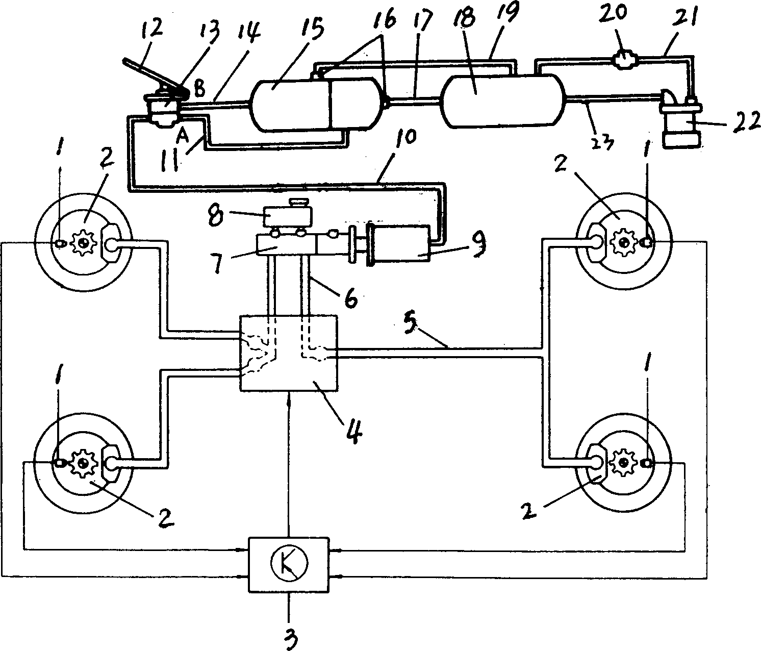
[0012] Such as figure 1 As shown, the gas-liquid mixing multi-live plug type brake system includes a multi-live plug hydraulic disc brake 2, a dispensing valve 4, a hydraulic main pump 7, a reservoir 8, a power chamber 9, a brake pedal 12, a gas pressure brake The control valve 13, the second storage barrel 15, the first gas cylinder 18, the air pump 22, the air passage of the air pump 22 is connected to the first storage cylinder 18, and there is a tuning on the sixth intake pipe 21 The pressure valve 20 is connected to the first storage cylinder 18 by the gas valve 20, and the first storage cylinder 18 is connected to the second storage barrel 15 by the fifth intake pipe 19, the fourth intake pipe 17, respectively. Pass, the fifth intake pipe 19, and the output port of the two mutually independent air chambers of the second storage gas barrel 15 is respectively provided by the second intake pipe 11 and the third intake pipe, respectively. 14 Connecting the input port A of the a...


PUM


Abstract

The invention relate to a automobile brake system. Gas liquid mixing multiple plunger disk brake system, It comprises a hydraulic disk brake(2), a hydraulic pump(7), a fluid storage jar(8), The piston of the hydraulic main pump(7) connected with the piston of the hydraulic sub pump of the hydraulic disk brake(2) via oil tube, Its characteristic is: the piston rod of the hydraulic main pump (7) connected with the air pressure piston rod of power air compartment (9), the air cavity of the power air compartment (9) connected with the output port of the air pressure brake control valve (13) via a first air pipe (10), The air pressure brake control valve (13) is equipped a brake pedal(12), the input port (A),input port (B) of the air pressure brake control valve (13) connected with the tow mutual independence gas houses of the gas storage or the gas storages via second air inlet pipe(11) and third inlet pipe(14) separately. The invention is provided with traits of strong brake press, small pedal force, short braking length and even force on the brake friction block.

Description

Technical field [0001] The present invention relates to an automotive brake system, and more particularly to a car disc brake system for automobiles. Background technique [0002] The automotive brake system is divided into a hydraulic brake system and a pressure brake system in accordance with the different braking medium. Hydraulic disc brake brake system generally mainly consists of hydraulic disc brake, hydraulic main pump, reservoir, brake pedal, and a piston cavity of the reservoir and hydraulic main pump, the piston chamber of the hydraulic main pump is from the tubing and The piston chamber of the hydraulic disc brake pump is connected, and the piston rod of the hydraulic main pump is connected to the brake pedal. Since the promotion of braking efficiency in the hydraulic brake system is mainly from the vacuum boost of the human and engine intake system, the vacuum boost of the engine intake system is very limited, in order to ensure sufficient braking efficiency, Also ma...

Claims


Application Information

Patent Timeline
Patent Type & Authority Applications(China)
IPC IPC(8): B60T11/10
Inventor 华林何耀华
Owner WUHAN UNIV OF TECH
Why Eureka
Try Eureka