Disc micromechanical top based on acoustic levitation

A micromachined gyroscope and acoustic levitation technology, which is applied in the direction of rotating gyroscope and gyroscopic effect for speed measurement, measurement device, etc., can solve the problems of low precision and efficiency, complex structure, etc. Weight reduction effect

Inactive Publication Date: 2006-02-08
SHANGHAI JIAO TONG UNIV
View PDF0 Cites 11 Cited by
  • Summary
  • Abstract
  • Description
  • Claims
  • Application Information

AI Technical Summary

Problems solved by technology

The disadvantages of the gyro with this driving mechanism are: due to the use of electromagnetic force, it cannot work in an environme

Method used


Image

  • Disc micromechanical top based on acoustic levitation

Examples


Embodiment Construction

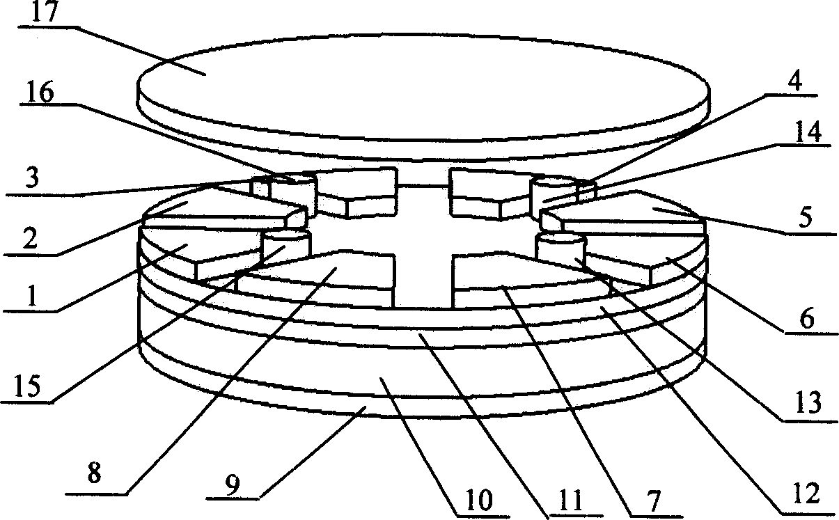
[0012] like figure 1 As shown, the present invention includes: eight capacitor plates 1, 2, 3, 4, 5, 6, 7, 8, partition electrodes 9, piezoelectric plates 10, base electrodes 11, insulating layers 12, and four support columns 13 . . 15, 16 on.

[0013] Capacitance plates 3, 8, 7, 4 and micro rotor 17 are combined to detect the left and right deflection angles of the micro rotor; capacitor plates 2, 1, 6, 5 and micro rotor 17 are combined to detect the front and rear deflection angles of the micro rotor.

[0014] The four supporting columns 13, 14, 15, 16 are all columnar. The support column is to prevent the contact and collision between the micro-rotor and the capacitor plate.

[0015] The piezoelectric plate 10 is polarized along the thickness direction.

[0016] The micro-rotor 17 is a circular metal disc.


PUM


Abstract

The invention relates to a disc micro-engine gyroscope based on the sound suspension in the field of micro motor technique. The invention comprises: eight capacitance plates, a partition electrode, a electricity plate, a base plate, a insulating layer, four bracing columns and a micro rotors, wherein the base plate and the partition electrode are positioned on two sides of the electricity plate along with the sickness direction; the insulating layer is positioned on the base plate; the eight capacitance plates are positioned on the insulating layer evenly, which forms four bracing columns on the insulating layer; the micro rotor is positioned on the four bracing columns.

Description

technical field [0001] The invention relates to a device in the field of micro-electromechanical technology, in particular to a disk micro-mechanical gyroscope based on acoustic levitation. Background technique [0002] Micromechanical gyroscope is an important inertial sensor, which is widely used in national defense, military and civilian fields. In recent years, with the development of micro-mechanical electronic systems (MEMS) processing technology, the research and development of micro-machined gyroscopes has attracted much attention. However, the current research is mainly on micromechanical vibrating gyroscopes. Most micromechanical vibrating gyroscopes use electrostatic force excitation and capacitive induction to measure angular velocity. Since the electrode gap cannot be made very small, generally around 1-2μm, and static electricity The excitation requires a large excitation voltage, which is not compatible with the IC circuit, and the accuracy will be significan...

Claims


Application Information

Patent Timeline
IPC IPC(8): G01C19/02G01P9/02
Inventor 刘景全杨斌陈迪
Owner SHANGHAI JIAO TONG UNIV
Why Eureka
Try Eureka