Broadband microstrip antenna and its feed matching device and method

A technology of microstrip antenna and feeding device, applied to antennas, antenna arrays, circuits, etc., can solve the problems of heavy antenna weight, increased cost, narrow bandwidth of microstrip antenna, etc., and achieve the effect of reducing radiation loss and improving efficiency

Inactive Publication Date: 2006-02-08
宁焕生
View PDF0 Cites 8 Cited by
  • Summary
  • Abstract
  • Description
  • Claims
  • Application Information

AI Technical Summary

Problems solved by technology

The thin metal layer 2 is formed by attaching a top-shaped metal sheet on the surface of the dielectric plate 1, or by corroding a thin metal layer of a certain shape on the surface of the dielectric plate covered with a thin metal layer. This manufacturing method is relatively Simple, but due to the ...

Method used


Image

  • Broadband microstrip antenna and its feed matching device and method
  • Broadband microstrip antenna and its feed matching device and method
  • Broadband microstrip antenna and its feed matching device and method

Examples


Embodiment Construction

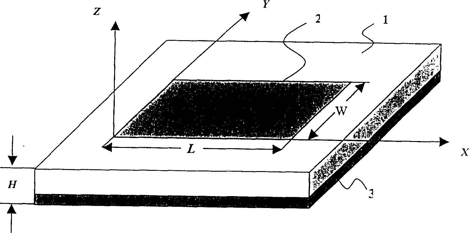
[0031] The present invention adopts air medium, because air has the dielectric constant ε less than other medium except air r , according to the microstrip antenna theory, the bandwidth of the microstrip antenna BW ~ 1 ϵ r h λ 0 where BW is the frequency bandwidth, W is the width of the microstrip patch unit, ε r is the dielectric constant of the medium used, h is the thickness of the medium, λ 0 is the wavelength of the emitted microwave. exist figure 1 In the prior art shown, the transmission medium adopts a dielectric plate 1, and its dielectric constant is ε r , the thickness is h, and its frequency bandwidth can be calculated. The present invention adopts air medium, and its dielectric constant ε r Compared with other media, it is the smallest, so the frequency bandwidth can be significantly increased. At the sa...


PUM


Abstract

Disclosed are a wide-band microstrip antenna and its feeder matching equipment and making method. The wide-band microstrip antenna comprises ground plate and microstrip paster unit, wherein between the ground plate and the microstrip paster unit has a distance and at least a supporting component for supporting and keeping the distance, and the supporting component is insulted with the group plate and microstrip paster unit. For the feeder matching equipment of the wide-band microstrip antenna, co-axial feeding lines goes through the ground plate and electrically connected with microstrip paster unit to make the input impedance of feeding point match with the feeding lines' impedance. The invention has the advantages of reducing radiation loss and of improving radiation efficiency.

Description

technical field [0001] The present invention relates to an antenna for communication, and in particular, the present invention relates to a high-frequency band antenna used for a transmitting / receiving end in radio communication, and a feeding matching device and method thereof. technical background [0002] Microstrip antenna is a new type of antenna developed in recent years, and it has been widely used in many fields such as aircraft, radar, broadband network, satellite, remote control, radio frequency identification and so on. attached figure 1 It is a perspective view of a common microstrip antenna. In general, a microstrip antenna includes a dielectric plate 1 as a substrate, a thin metal layer 2 coated on the dielectric plate 1 as a patch unit and a The ground metal plate 3 on the other side of the thin metal layer 2. The thin metal layer 2 is formed by attaching a top-shaped metal sheet on the surface of the dielectric plate 1, or by corroding a thin metal layer of...

Claims


Application Information

Patent Timeline
IPC IPC(8): H01Q13/08H01Q1/38H01Q21/00
Inventor 宁焕生薛明华刘文明王宝发刘铁军
Owner 宁焕生
Why Eureka
Try Eureka