Check patentability & draft patents in minutes with Patsnap Eureka AI!

Birefringent optical component

A technology of optical components and optical elements, which is applied in the direction of optical recording head, optical recording/reproduction, beam source, etc., which can solve the problems of blurred focus spot and loss of fidelity

Inactive Publication Date: 2006-02-08
KONINKLIJKE PHILIPS ELECTRONICS NV
View PDF0 Cites 2 Cited by
  • Summary
  • Abstract
  • Description
  • Claims
  • Application Information

AI Technical Summary

Problems solved by technology

This leads to blurring of the focal spot, and subsequent loss of fidelity in the readout of the disc

Method used


Image

  • Birefringent optical component
  • Birefringent optical component
  • Birefringent optical component

Examples


Embodiment Construction

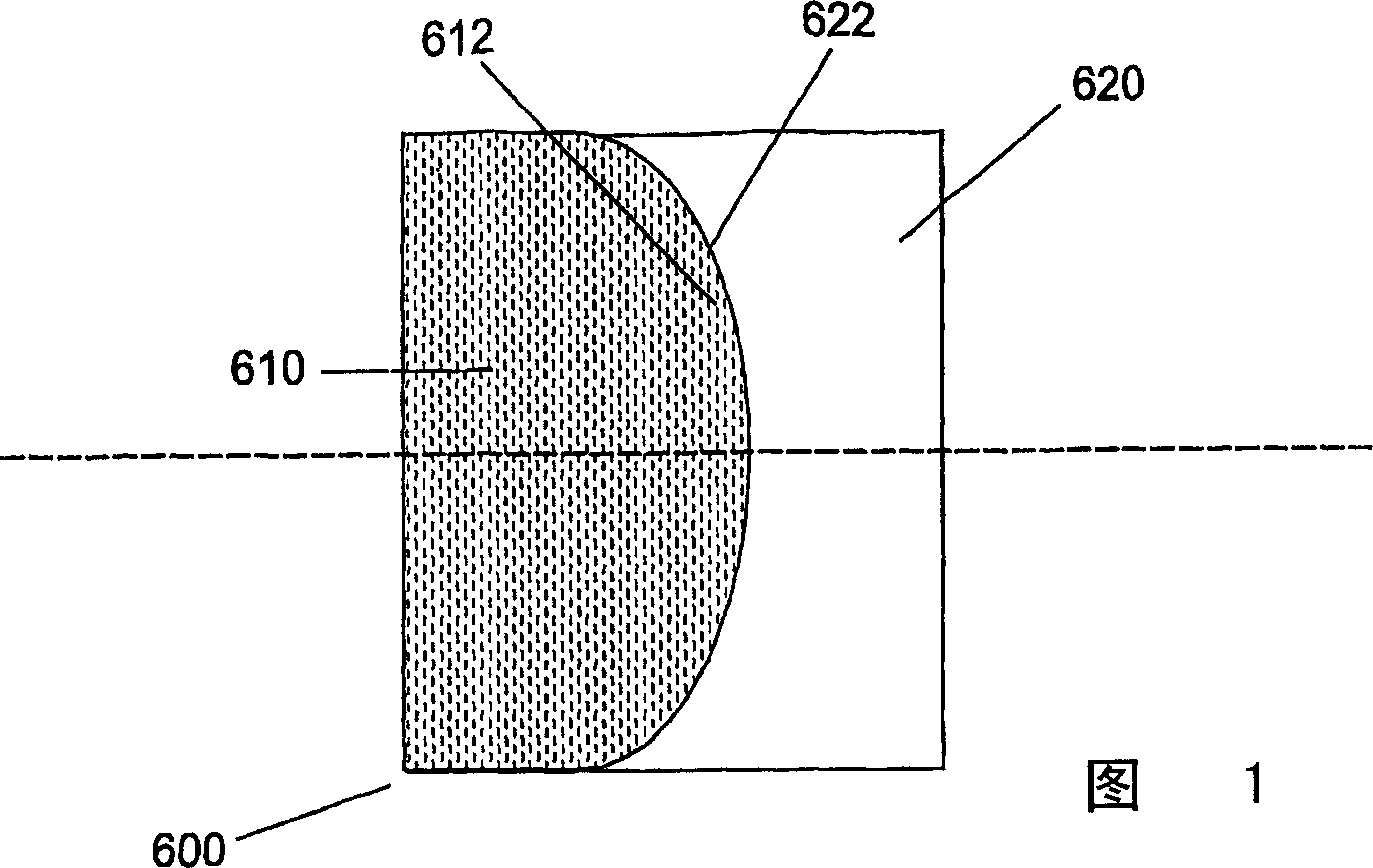
[0021] An optical component (or part of an optical component, an optical element) may include curved surfaces to focus light (eg, a convex lens) or to diverge light (eg, a concave lens). Depending on the angle at which the polarized radiation beam is incident on the birefringent optic with curved surfaces, the optic will provide different focusing or diverging effects.

[0022] Likewise, other component optical functions are provided by other shaped (ie, non-planar) surfaces, such as step functions and gratings.

[0023] The inventors of the present invention have realized that by providing additional material adjacent to the curved (or otherwise shaped) surface, if the refractive index of the additional material is substantially equal to the refractive index of the birefringent material at a predetermined angle, then when polarized light is At a predetermined angle of incidence on the surface (ie, the interface between the birefringent material and the add-on material), the s...


PUM


Abstract

An optical component ( 600, 181 ) comprises two adjacent materials ( 610, 620 ) with a shaped ( e.g. curved ) interface between the materials ( 612, 622 ). The first of the materials ( 610 ) is birefringent. The second material ( 620 ) has a refractive index substantially equal to the refractive index of the birefringent material at a predetermined angle.

Description

field of invention [0001] The present invention relates to optical components comprising birefringent materials, devices comprising such components, and methods of making such components and devices. The component is particularly suitable, but not limited, for use as an optical element in an optical scanning device. Background of the invention [0002] Optical pickup units for use in optical scanning devices are known. This optical pickup unit is mounted on a movable carriage for scanning on a track of an optical disc. It is preferable to keep the size and complexity of the optical pickup unit as small as possible in order to reduce manufacturing costs and to allow additional space for other components installed in the scanning device. [0003] Modern optical pickup units are generally compatible with at least two different optical disc formats, such as compact disc (CD) and digital versatile disc (DVD) formats. The Blu-ray Disc (BD) format has recently been proposed, whi...

Claims


Application Information

Patent Timeline
Patent Type & Authority Applications(China)
IPC IPC(8): G11B7/125G11B7/135G11B7/00
CPCG11B7/1378G11B7/13925G11B2007/0013G11B2007/0006G11B7/1369G11B7/1365G11B7/1372
Inventor E·J·K·维斯特根
Owner KONINKLIJKE PHILIPS ELECTRONICS NV
Features
  • R&D
  • Intellectual Property
  • Life Sciences
  • Materials
  • Tech Scout
  • Unparalleled Data Quality
  • Higher Quality Content
  • 60% Fewer Hallucinations
Learn More