Textile machinery with air flow delivery unit and filtering unit

A technology of textile machinery and air conveying, which is applied in the direction of continuous winding spinning machine, spinning machine, textile and paper making, etc., can solve the problems of pollution, loss of filtering effect, influence of wool yarn, etc., and achieves low cost and simple geometry. Effect

Inactive Publication Date: 2006-02-15
利特英格纺织机械制造股份公司
View PDF0 Cites 1 Cited by
  • Summary
  • Abstract
  • Description
  • Claims
  • Application Information

AI Technical Summary

Problems solved by technology

The disadvantage of existing solutions is that such filter devices often need to be decontaminated by the operator of the textile machine in a relatively short period of time
It is also often the case that filter equipment becomes contaminated very slowly, so that people do not notice it until m

Method used


Image

  • Textile machinery with air flow delivery unit and filtering unit
  • Textile machinery with air flow delivery unit and filtering unit
  • Textile machinery with air flow delivery unit and filtering unit

Examples


Embodiment Construction

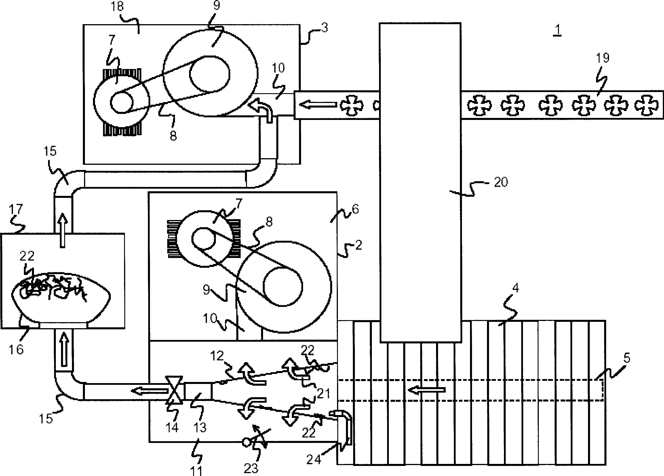
[0039] figure 1 A possible embodiment of the textile machine 1 of the invention is given in . The textile machine 1 is an open end spinning machine. It consists of mechanical lower part 2 and mechanical upper part 3. The mechanical lower part 2 has a large number of working positions 4 which receive vacuum via vacuum lines 5 . Furthermore, the mechanical lower part 2 also has a first air conveyor 6 whose function is to generate a negative pressure. The first air conveyor 6 is driven by an electric motor 7 which drives a blower 9 via a belt 8 . The inlet side 10 of the blower 9 is connected to a vacuum chamber 11 in which a conical filter 12 is located. The conical filter 12 is connected on the inlet side to the vacuum line 5 and on the outlet side to the cylindrical section 13 . Behind the cylindrical section 13 there is an adjusting device 14 which can be in the form of a gas flow valve or a flap and regulates the flow path via a conveying device 15 .

[0040] The conve...


PUM


Abstract

The present invention provides an open-ended textile spinning machine having numerous work stations, comprising at least one center pneumatic conveyer to generate a differential pressure, the differential pressure is acted for making each work station process, and a filter for purifying air current, the rear one is pumped and passed the pneumatic conveyer. According to the invention, the characteristic of the textile spinning machine is that the air current passes the first filter by the action of the differential pressure generated by the center pneumatic conveyer, and designs at least one outlet besides the filtering channel in the first filtering mean, connected to the second filtering mean by one side of the conveyer, and a regulating mean for making the air current passing the first filtering mean change to the outlet in a certain time.

Description

technical field [0001] The invention relates to a textile machine with an air conveyor and a filter device, in which there are a large number of working positions, and in particular to an open-port worsted spinning machine, which has at least one central air conveyor to generate a pressure difference, wherein the The pressure difference is used to operate the various working positions, and the filter device is used to purify the air flow drawn through the air conveyor. In addition, the present invention also relates to a method for purifying a filter device in a textile machine, especially in an open-ended spinning machine, in which the exhaust gas at the working position needs to be purified. Background technique [0002] In order to make each working position of the textile machinery work, there are many reasons to design and install a negative pressure source on each working position. For this purpose, existing air conveyors are used which are placed in the center of the...

Claims


Application Information

Patent Timeline
IPC IPC(8): D01H4/22D01H11/00
CPCD01H11/005D01H4/22
Inventor B・施汤K・措普夫
Owner 利特英格纺织机械制造股份公司
Why Eureka
Try Eureka