Control handle head of mobile floor delivery tool and moving speed conveyor

A technology for controlling handles and ground transportation, which is applied to the layout of power plant control mechanisms, motor vehicles, transportation and packaging, etc. It can solve the problems of high wear and failure of micro switches, collision between magnet bracket and Hall sensor, labor-intensive problems, etc. , to achieve the effect of improving mechanical stability, firm and mechanical connection, and stable mechanical connection

Active Publication Date: 2006-02-22
REMA LIPPRANDT GMBH & CO KG
View PDF2 Cites 11 Cited by
  • Summary
  • Abstract
  • Description
  • Claims
  • Application Information

AI Technical Summary

Problems solved by technology

[0029] A simultaneous problem is the high wear failure of the microswitches as they are operated every time the ammo advances and reverses
[0030] In addition, correcting the position of the Hall sensor with the connection pins away from the magnet bracket in the direction perpendicular to the board is a labor-intensive task because the Hall sensors are soldered on three connection pins, and Need to align
[0031] At the same time, as mentioned above, in the event of bending of the connecting pins, there is a risk of the magnet carrier colliding with the Hall sensor

Method used


Image

  • Control handle head of mobile floor delivery tool and moving speed conveyor
  • Control handle head of mobile floor delivery tool and moving speed conveyor
  • Control handle head of mobile floor delivery tool and moving speed conveyor

Examples


Embodiment Construction

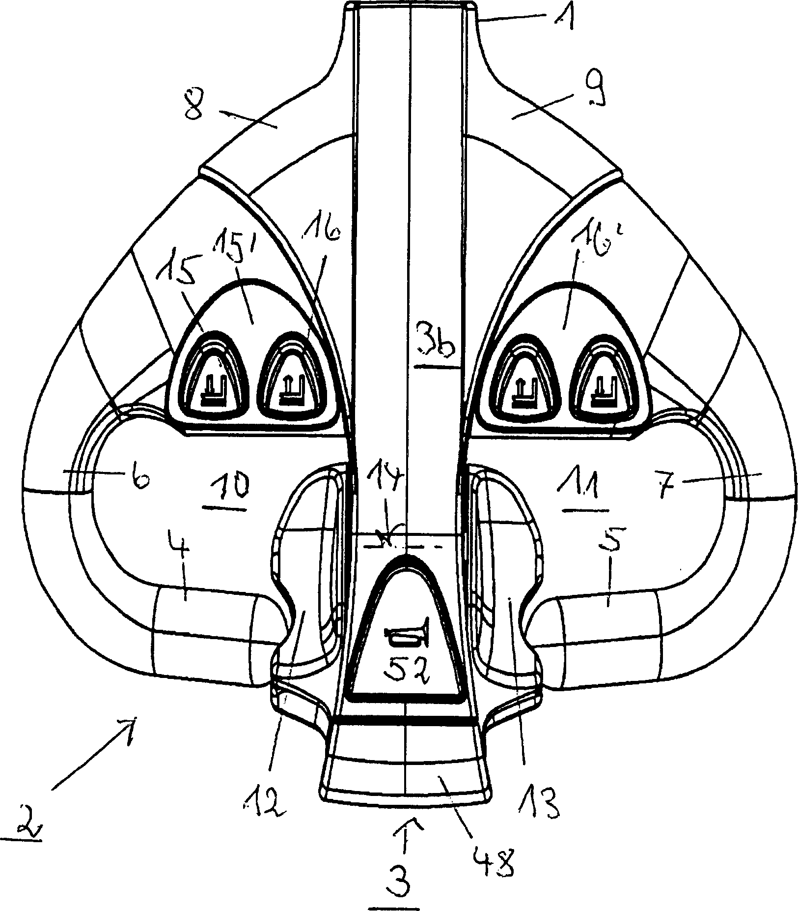
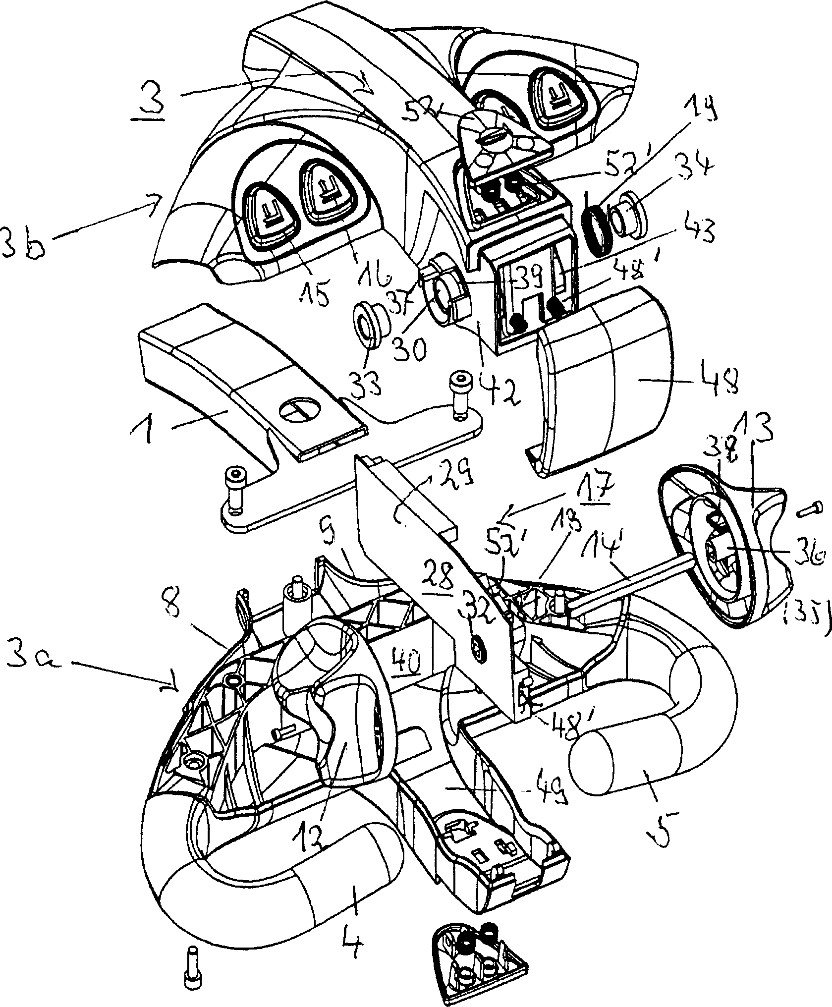
[0164] figure 1 and figure 2 The control handle head (2) of the ground vehicle shown in (3) centerline both sides left and right are the variable-speed handwheels (12,13) ​​that are formed by two cams for manipulation, like a wing wheel. In addition, there are control buttons (15, 16) concentrated on both sides of the control handle horn (3) at the control handle head (2), so that it is convenient for both hands to hold on the handle (4, 5) with one hand or two hands thumb to operate. As the common practice of ground vehicles, there is a body protection switch (48) at the outer end of the control handle horn (3) of the control handle head (2).

[0165] according to figure 1 and figure 2 , the head of the control handle (2) has an inclined surface or a basin-shaped surface (15', 16') to protect the control switch (15, 16) within the range of the control handle horn (3), and the basin-shaped surface is preset to control The handles (4, 5) of the device horns are tilted. ...


PUM


Abstract

The device contains a Hall sensor (18') for controlling traveling movement of the vehicle, whose output signal is proportional to the angle of rotation of the drive switch handle and / or a magnet carrier (20) with two permanent magnets (21,22). The Hall sensor is securely mounted so that faulty radial and axial movements transferred to the rotation shaft (14') of the magnet carrier do not cause drive signal errors. An independent claim is also included for a drive value generator for a measurement arrangement for generating control signals for propulsion drive control.

Description

technical field [0001] The invention relates to a special control handle head for a motorized ground vehicle according to the general concept of claim 1 . [0002] In addition, the present invention also relates to a travel speed value transmitter of a measuring device belonging to an operation control system according to the superordinate concept of claim 1 and claim 21 . Background technique [0003] Through the variable speed handwheel supported on the right and left sides of the horn of the control handle, the forward, backward and speed of the ground conveying tool can be adjusted by turning, because the rotating shaft of the variable speed handwheel is connected with a proportional switch, and the proportional switch produces such as control The adjustment signal required to operate the drive can also be used for the lift control, swivel control or tilt control as long as it is associated with the angle of rotation of the variable speed handwheel. [0004] It has been...

Claims


Application Information

Patent Timeline
Patent Type & Authority Applications(China)
IPC IPC(8): B60K26/02B62B3/06B66F9/20
CPCB62B5/06B66F9/20B62B5/063
Inventor K・施坦德克
Owner REMA LIPPRANDT GMBH & CO KG
Why Eureka
Try Eureka