Mould holder

A retainer and mold technology, applied in the field of mold retainers, can solve problems such as increased workpiece cost and unfavorable product appearance.

Inactive Publication Date: 2006-02-22
SPG PRE SERIES TOOLING & PROTOTYPING
View PDF0 Cites 0 Cited by
  • Summary
  • Abstract
  • Description
  • Claims
  • Application Information

AI Technical Summary

Problems solved by technology

Flash removal requires considerable post-processing costs and is detrimental to the appearance of the product
[0005] Even with small batch sizes, the cost of the workpiece increases significantly if post-processing steps are required

Method used


Image

  • Mould holder

Examples


Embodiment Construction

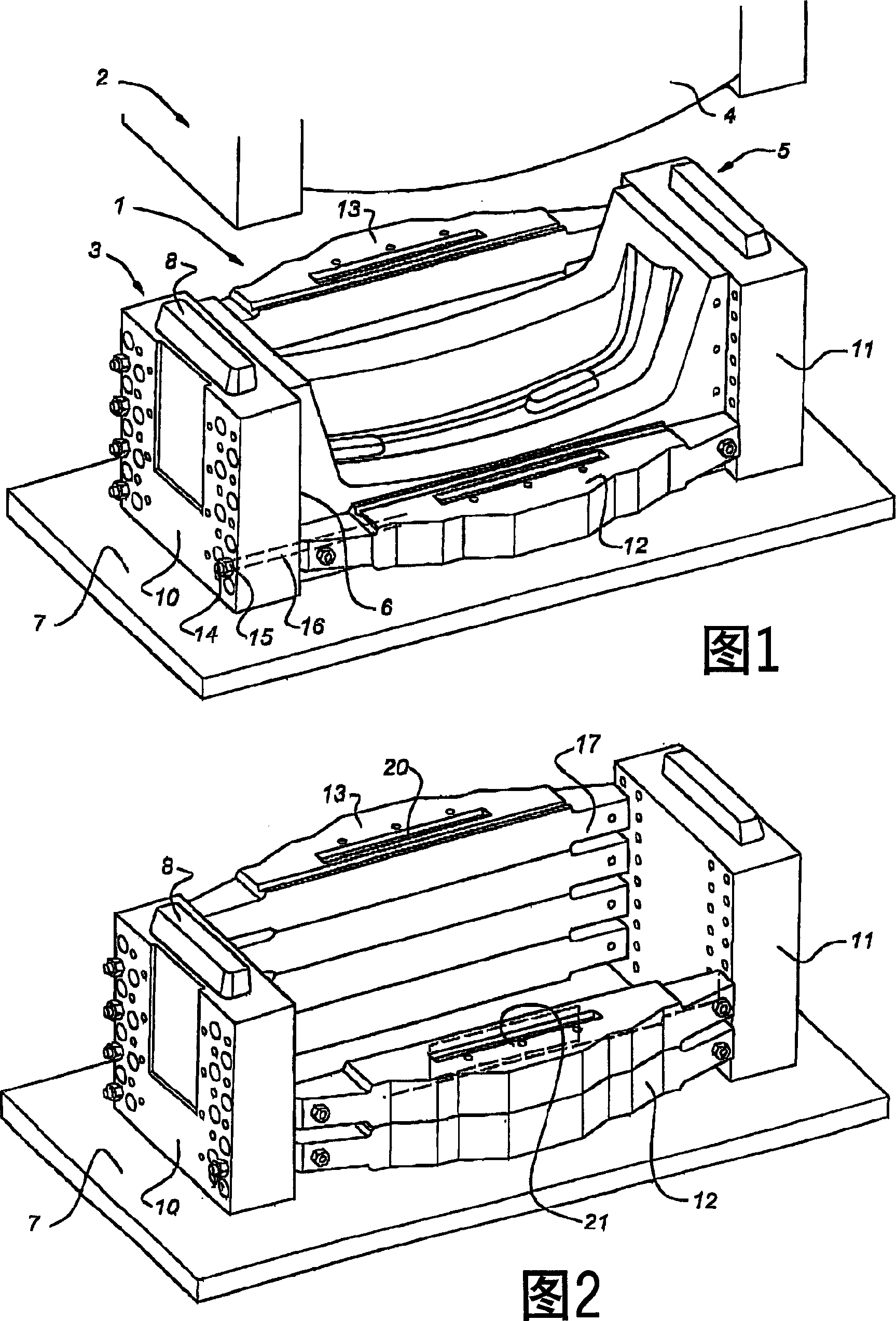
[0016] In FIGS. 1 and 2 , the mold assembly according to the invention is generally indicated with reference numeral 1 . It comprises an upper holder 2 , shown only highly schematically, provided with an upper mold part 4 . The lower holder 3 and the lower mold part 5 arranged therein are shown in more detail. A housing portion 6 in which the lower mold part is accommodated is defined in the lower holder. The lower mold part is provided with a plate 7 for fixing to the injection molding machine, while also having a centering ridge 8 interacting with the upper holder 2 to center the mold parts relative to each other.

[0017] The lower holder comprises end pieces 10 and 11 arranged opposite to each other with spacers 12, 13 interposed therebetween. There is also a tension rod 14 extending through a hole 16, which rod is provided with a nut 15 near its end. There are tension rods in the lower and upper spacers 12 , 13 and they extend through holes 18 in the end pieces 10 , 11...


PUM


Abstract

Mould holder (2, 3) comprising an accomodation (6) for enclosing a mould part (4, 5) and a fixing for fixing (7) to an injection moulding machine. The mould holder consists of at least two parts (10, 11) located opposite one another which are fixed to one another with prestressing, accommodating the relevant mould part between them. This prestressing can be applied using tensioning rods (14). Moreover, it is possible to apply prestressing by hydraulic means (20, 21). In the latter case the prestressing is not applied continuously but only when the injection cavity is closed.

Description

technical field [0001] The invention relates to a mold holder comprising a receptacle for receiving a mold part and a fixing part for fixing to an injection molding machine. Background technique [0002] Such mold holders are generally known in the prior art and are used to impart rigidity to relatively weak mold parts. Especially when relatively small batches / scales of products have to be produced, for example up to about 1000 pieces, the mold parts in which the shape of the product to be injection molded has already been formed are separated from the mold holder. In this case, the high cost of making a complete mold is not justified compared to this batch size. Particular batch sizes and prototypes are to be considered here. In this case, the mold part is made, for example, of easily machined aluminum or another easily machined material. [0003] If the mold becomes larger, the forces acting on it for a given injection pressure will be considerable. Large molds are use...

Claims


Application Information

Patent Timeline
Patent Type & Authority Applications(China)
IPC IPC(8): B29C45/17B29C45/26
CPCB29C45/2675
Inventor 亚伯拉罕·海斯贝特·德科宁
Owner SPG PRE SERIES TOOLING & PROTOTYPING
Why Eureka
Try Eureka