Dimming ballast control IC with flash suppression circuit

A technology of electronic ballasts and ballasts, applied in the direction of circuits, electric light sources, control/regulation systems, etc., can solve problems such as problems caused by electronic ballasts

Inactive Publication Date: 2006-02-22
INTERNATIONAL RECTIFIER COEP
View PDF1 Cites 5 Cited by
  • Summary
  • Abstract
  • Description
  • Claims
  • Application Information

AI Technical Summary

Problems solved by technology

[0005] Electronic ballasts can cause problems during start-up of fluorescent lamps when operating fluorescent lamps in dimming mode

Method used


Image

  • Dimming ballast control IC with flash suppression circuit
  • Dimming ballast control IC with flash suppression circuit
  • Dimming ballast control IC with flash suppression circuit

Examples


Embodiment Construction

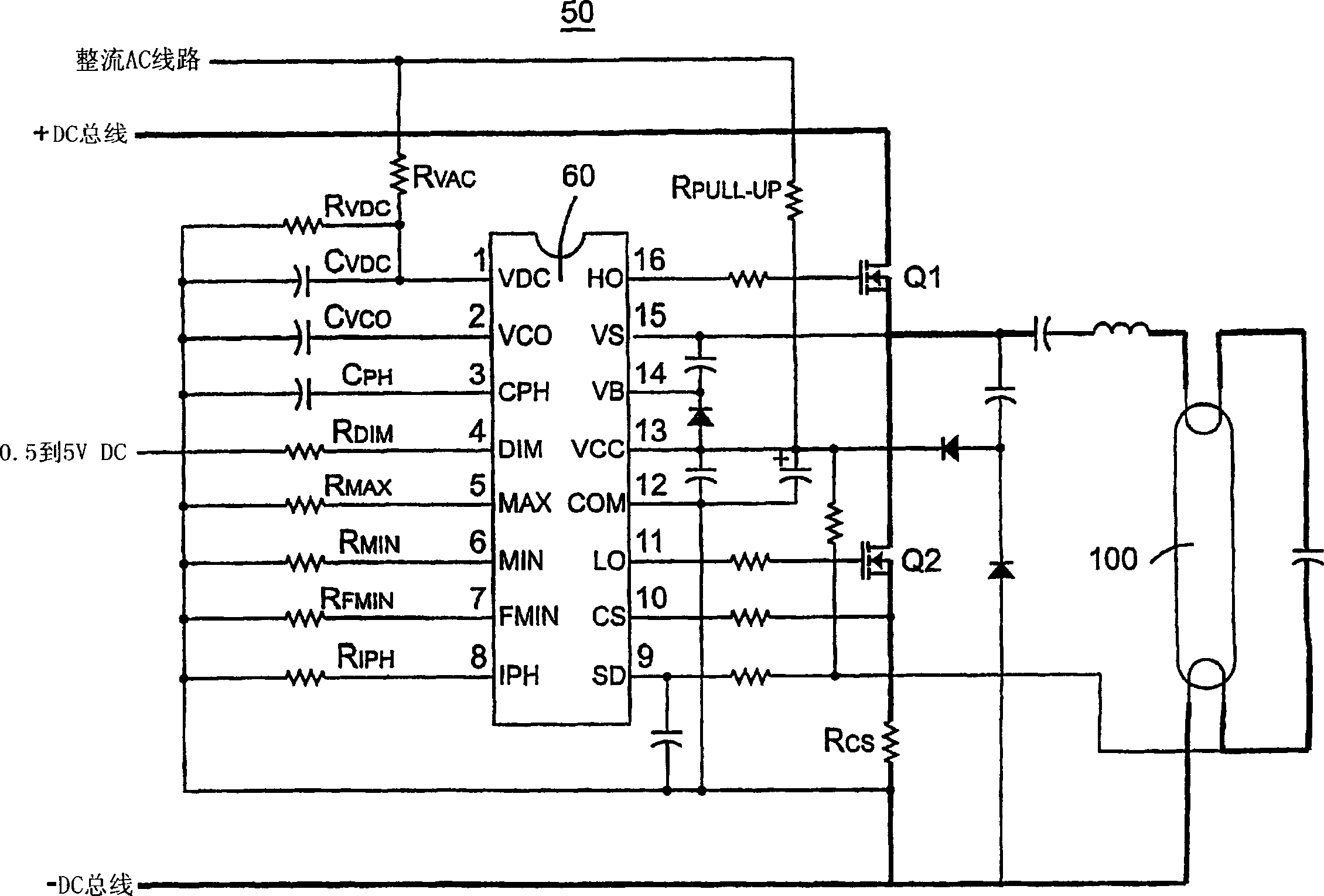
[0029] The present invention provides improvements in dimming electronic ballasts controlled to prevent lamp flicker. now refer to figure 1 , the circuit 50 is illustrated as a circuit 50 specially provided for an electronic ballast. The electronic ballast operates the fluorescent lamp 100 according to input settings and parameter selections. The electronic ballast operates with a half-bridge consisting of two switches including a high-side switch Q1 and a low-side switch Q2. Switches Q1 and Q2 are operated by electronic ballast control IC 60 in accordance with input commands and parameter settings provided by external components on control IC 60 . Control IC 60 provides ballast control and half-bridge driver within a single IC and is capable of sensing lamp power without the use of an inverter. The control IC 60 provides closed loop lamp power control and preheat current control, the preheat time and current being programmable by external components. The control IC 60 als...


PUM


Abstract

A dimming electronic ballast control provides flash suppression by igniting the fluorescent lamp at a high power level, and then reducing the power output level to the appropriate dimming set level. The electronic ballast includes an integrated circuit that uses closed loop phase control and a VCO to control a switching frequency of a half bridge, which in turn controls power delivered to the fluorescent lamp. Current through the half bridge is sensed to provide closed loop control. The current sense signal is used to provide a high power level in the electronic ballast during ignition of the lamp, and as a phase detector for the phase control. A rate of change control circuit controls the speed of adjustment between power level settings, especially during ignition of the lamp. The electronic ballast provides a wide linear dimming range with fault detection and flash suppression.

Description

[0001] related application [0002] This application is based upon and claims the benefit of U.S. Provisional Application No. 60 / 440,926, entitled "Dimming Ballast Control IC with Flash Suppression Circuit," filed January 16, 2003 , the priority of which is hereby claimed, and is incorporated by reference in its entirety. technical field [0003] The present invention relates generally to electronic ballasts for fluorescent lamps, and more particularly to electronic ballast controls that prevent fluorescent flicker. Background technique [0004] Electronic ballasts for fluorescent lamps are well known, especially those operating with a switched half-bridge. Such an electronic ballast is described in US Patent No. 6,008,593 to International Rectifier Corporation. Electronic ballast controllers have been developed to include dimming functionality, especially full linear dimming control. One type of dimming control is illustrated in US Patent No. 6,008,593 to International R...

Claims


Application Information

Patent Timeline
Patent Type & Authority Applications(China)
IPC IPC(8): G05F1/00H05B41/392
CPCY10S315/07H05B41/3921Y10S315/04
Inventor T·里巴里希
Owner INTERNATIONAL RECTIFIER COEP
Why Eureka
Try Eureka