Actuator device
A technology of actuating device and loading and unloading, applied in the direction of transmission parts, electromechanical devices, electric components, etc., can solve problems such as deteriorating operation and failure
- Summary
- Abstract
- Description
- Claims
- Application Information
AI Technical Summary
Problems solved by technology
Method used
Image
Examples
Embodiment 1
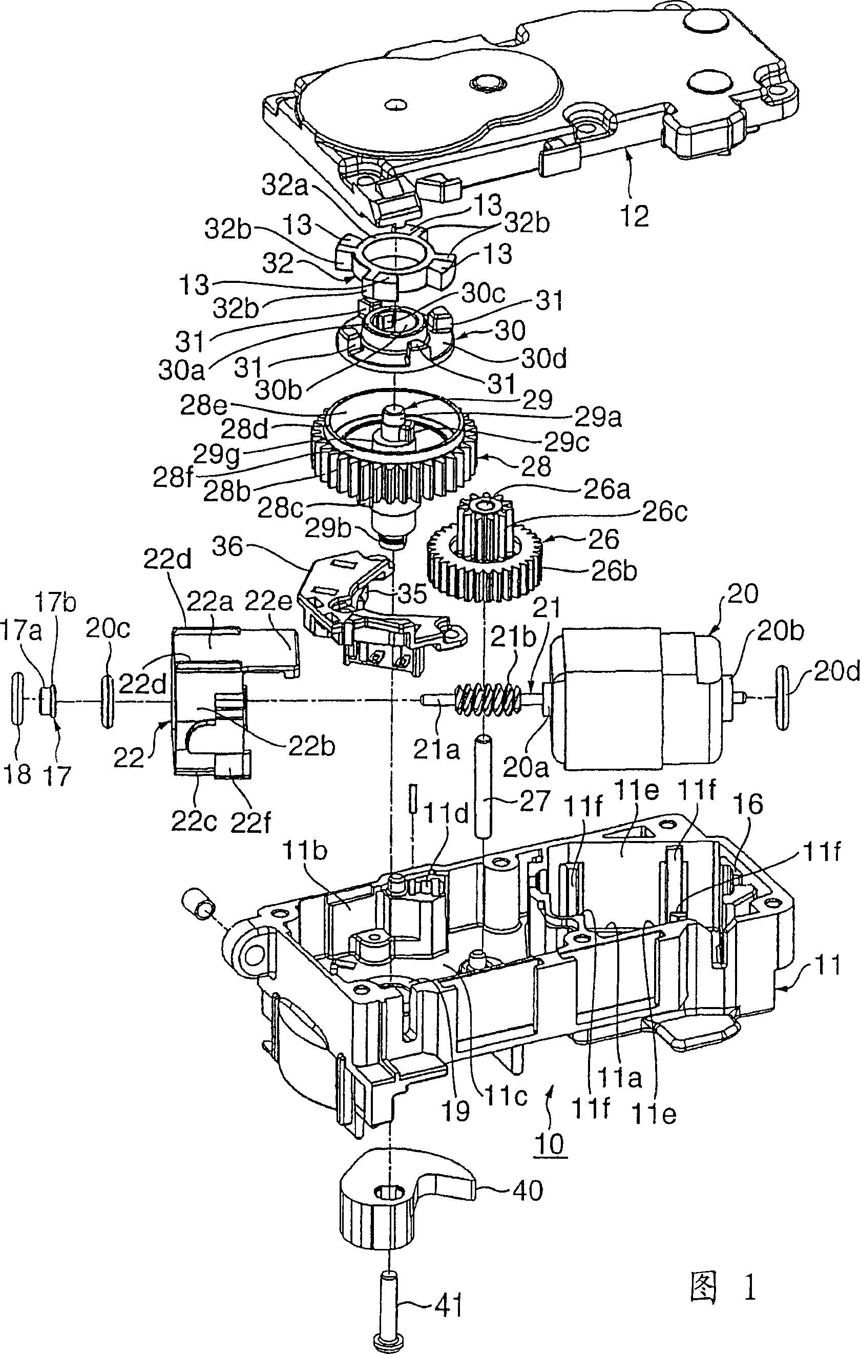
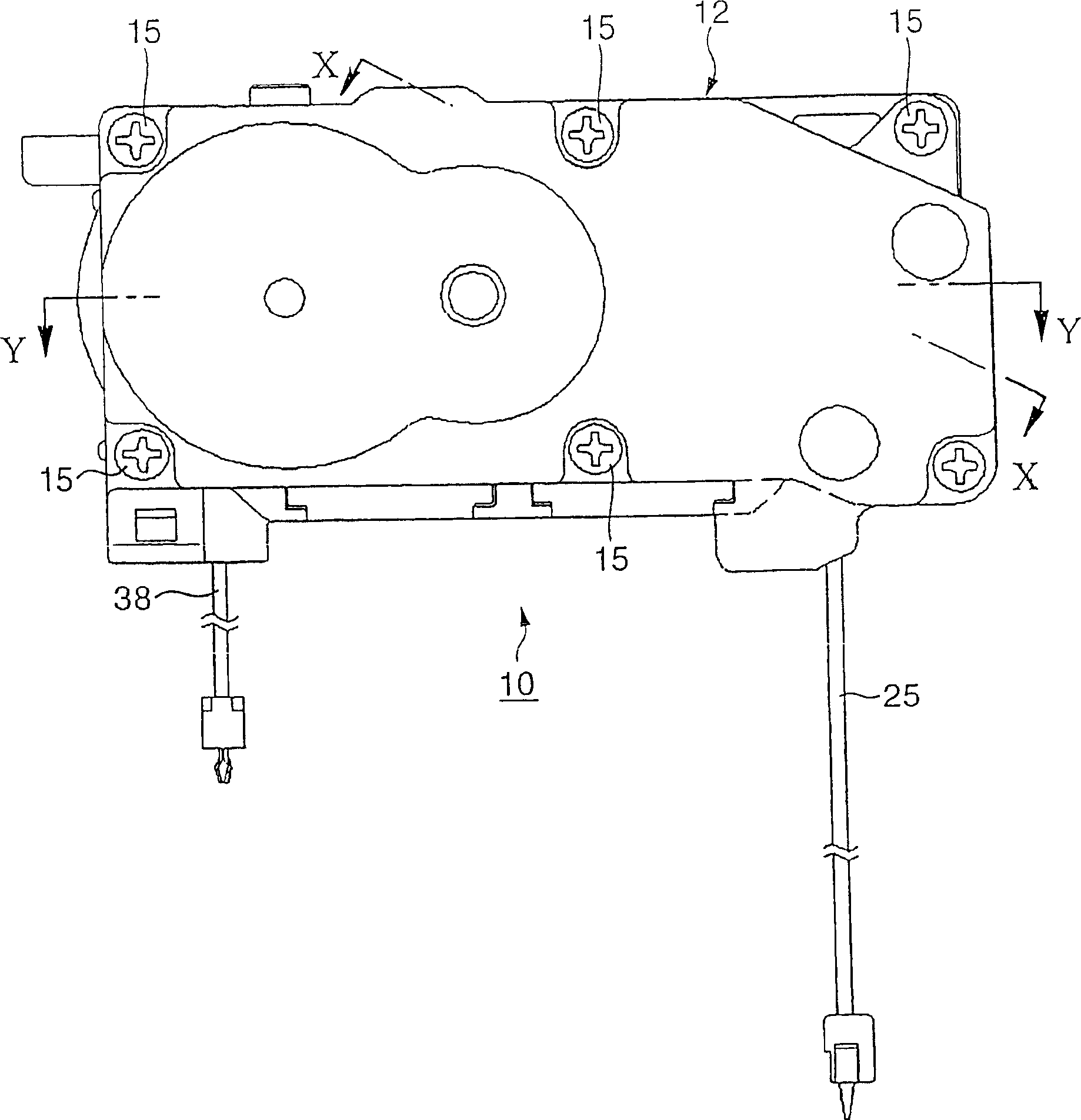
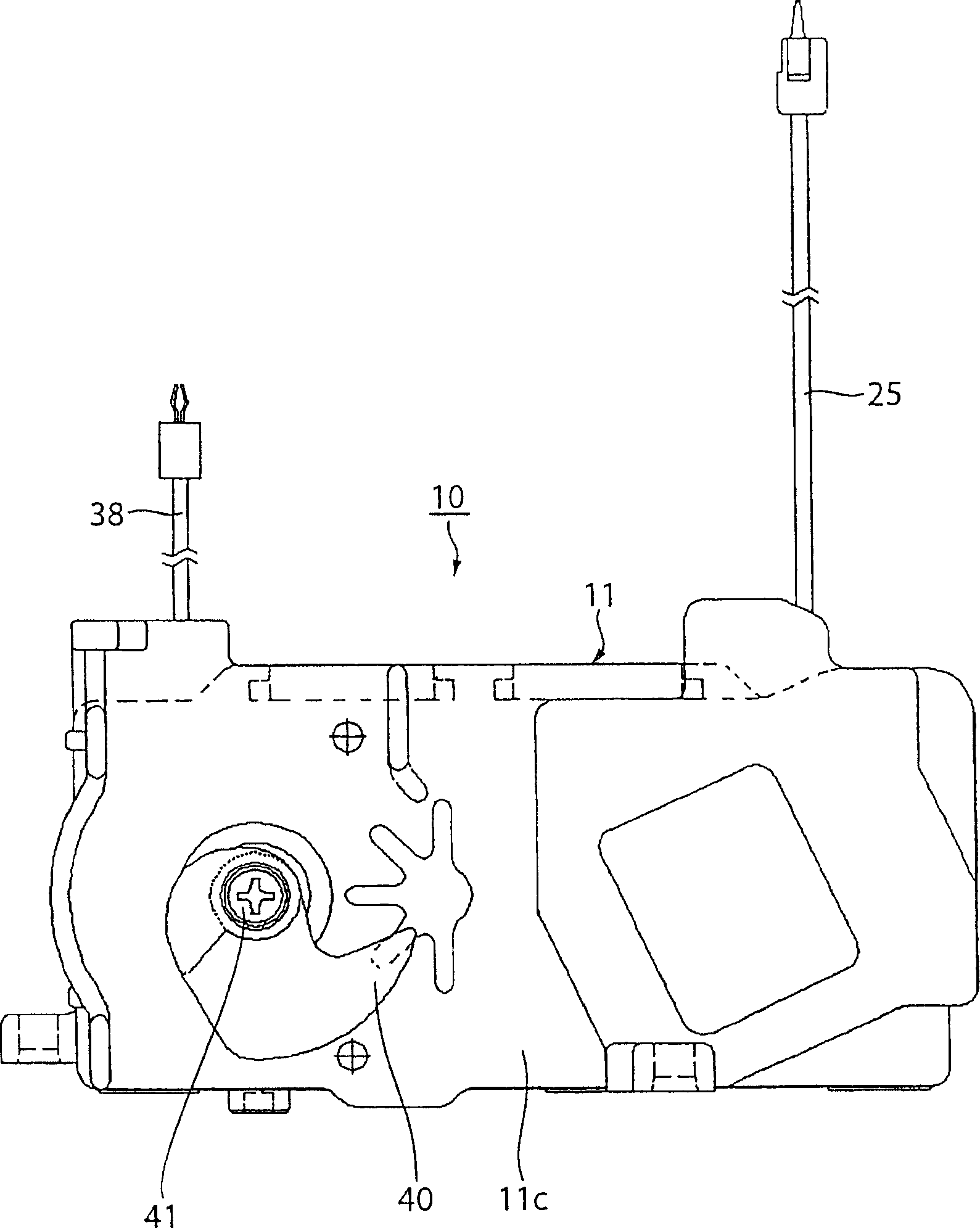
[0058] Fig. 1 is an exploded perspective view of a manipulation locking device according to Embodiment 1 of the present invention, figure 2 is the plan view of the device, image 3 is the bottom view of the device, Figure 4 is a perspective view of the device viewed from the bottom side, Figure 5 is the rear view of the device, Figure 6 is the plan view of the inside of the device chassis, and Figure 7 is along the figure 2 The cross-sectional view developed by the line X-X, Fig. 8 is a side view of the motor used in the device, Figure 9 It is a plane view of the motor, Fig. 10A is a rear view of the cylindrical elastic member installed in the motor, Fig. 10B is a side view of the elastic member, Figure 10C is the plan view of the elastic member, Figure 11A is an enlarged sectional view showing the terminal connection portion of the motor, Figure 11B is an enlarged sectional view showing a state where a terminal is connected to a terminal connection part, Figu...
Embodiment 2
[0081] Such as Figure 6 As shown, a pair of sidewalls 11e, 11e extending in parallel in the up-down direction are formed at both sides of the two side walls 11e, 11e of the motor housing portion 11a of the chassis 11 (in the vicinity of the corresponding corner portions) by integrally protruding respectively. The protruding portions 11f, 11f and floatingly support the motor 20 via the cylindrical elastic member 22 between the two side walls 11e, 11e of the motor accommodating portion 11a via respective protrusions of the two side walls 11e, 11e of the motor accommodating portion 11a The bending (deformation) of the armature shaft 21 of the motor 20 caused by the reaction force F from the reduction gear 26 meshing with the worm 21b of the armature shaft 21 of the motor 20 and the displacement in the motor accommodating portion 11a It can be positively limited within respective predetermined ranges, and the occurrence of malfunction or noise, etc., caused by bending of the arma...
Embodiment 3
[0084] Such as Figure 6 As shown in FIG. 10, the elastic member 22 is formed in a cylindrical shape from a resin material such as thermoplastic elastomer. That is, the elastic member 22 is made cylindrical by an upper wall portion (upper portion) 22a, two side wall portions (two side portions) 22b, 22b, and a bottom wall portion (bottom) 22c. The respective outer shapes of the upper wall portion 22a and the bottom wall portion 22c of the elastic member 22 respectively integrally protrude to form respective pairs of protruding portions 22d, 22d extending in parallel in the front and rear directions. As shown in FIG. 7, respective pairs of projecting portions 22d, 22d respectively intersect projecting portions 11g, 11g of the bottom wall 11c of the pair of motor accommodating portions 11a and a pair of projecting portions integrally protruding so as to form the inner surface 12a of the case cover 12. Protruding portions 12g, 12g. Accordingly, the motor 20 is floatably support...
PUM
 Abstract
Description
Claims
Application Information
 - R&D
- Intellectual Property
- Life Sciences
- Materials
- Tech Scout
- Unparalleled Data Quality
- Higher Quality Content
- 60% Fewer Hallucinations
Browse by: Latest US Patents, China's latest patents, Technical Efficacy Thesaurus, Application Domain, Technology Topic, Popular Technical Reports.
© 2025 PatSnap. All rights reserved.Legal|Privacy policy|Modern Slavery Act Transparency Statement|Sitemap|About US| Contact US: help@patsnap.com


