Supercharge Your Innovation With Domain-Expert AI Agents!

Photomask and method for creating a protective layer on the same

A photomask and protective layer technology, applied in the field of photolithography, can solve the problems of reducing image quality, not removing photomask pollutants, etc., and achieve the effect of strong resistance

Inactive Publication Date: 2006-03-01
TOPPAN PHOTOMASKS INC
View PDF0 Cites 6 Cited by
  • Summary
  • Abstract
  • Description
  • Claims
  • Application Information

AI Technical Summary

Benefits of technology

This patented method involves creating an oxide film (a thin coating) over the entire area where some parts of the mask have been removed during manufacturing processes for semiconductor devices such as integrated circuits. By exposure to light with high intensity, this oxidized portion becomes harder than others without it being affected negatively due to factors like abrasions. To prevent damage to sensitive areas, there should also be enough protection against corrosion attacks while still allowing clear access when needed. Additionally, if any defects occur after processing, they must be repairable through re-cleaning techniques.

Problems solved by technology

This patented technical problem addressed in this patents relates to improving the accuracy and reliability of forming high-quality opaque layers (such as chrome) over large areas of silicon wafers due to impurity particles introduced into them when they pass through the etchings step after being processed. These impurities affect how well the light passes through the transparent materials like those made up of chromium plating. To address this issue, it has been proposed to improve the purity level of certain regions within the structure's underlying film while minimizing variations in other parameters involved in processing steps.

Method used


Image

  • Photomask and method for creating a protective layer on the same
  • Photomask and method for creating a protective layer on the same
  • Photomask and method for creating a protective layer on the same

Examples


Embodiment Construction

[0021] refer to Figure 1 to Figure 6 , where the same numerals are used to designate the same or corresponding parts, for the best understanding of the preferred embodiment of the present invention and its advantages.

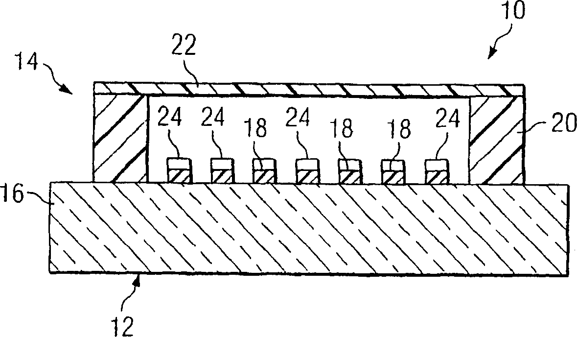
[0022] figure 1 Shown is a cross-sectional view of a photomask assembly 10 that may be inspected by automatically transferring defect images from an inspection system to a database. Photomask assembly 10 includes photomask 12 coupled to pellicle assembly 14 . Substrate 16 and patterned layer 18 collectively form part of photomask 12 . Photomask 12 may also be described as a mask or reticle, which may have a variety of sizes and shapes including, but not limited to, generally circular, circular, rectangular, or square. The photomask 12 can also be any type of photomask including, but not limited to, a disposable master, a 5-inch reticle, a 6-inch reticle, a 9-inch reticle, or one that can be used to project an image of a circuit pattern onto a semiconductor ...


PUM


Abstract

A photomask and method for creating a protective layer on the photomask are disclosed. The method includes placing a photomask including a patterned layer formed on at least a portion of a substrate in a chamber. Oxygen is introduced into the chamber proximate the patterned layer and the photomask is exposed to radiant energy that initiates a reaction between the oxygen and the patterned layer in order to passivate the patterned layer and prevent optical properties of the patterned layer from being altered by a cleaning process.

Description


Claims


Application Information

Patent Timeline
Owner TOPPAN PHOTOMASKS INC
Features
  • R&D
  • Intellectual Property
  • Life Sciences
  • Materials
  • Tech Scout
  • Unparalleled Data Quality
  • Higher Quality Content
  • 60% Fewer Hallucinations
Learn More