Vehicle deceleration control apparatus

A control device and deceleration technology, which is applied in the direction of power devices, control drives, vehicle components, etc., can solve problems such as undiscussed relations and problems with vehicle deceleration control devices

Active Publication Date: 2012-10-03
TOYOTA JIDOSHA KK
View PDF8 Cites 0 Cited by
  • Summary
  • Abstract
  • Description
  • Claims
  • Application Information

AI Technical Summary

Problems solved by technology

Although the provision of these "Decel" and "Can-Decel" switches facilitates the setting of the target deceleration value, when the shift lever and the "Decel" and "Can-Decel" switches are operated independently of each other, the vehicle deceleration control device T

Method used


Image

  • Vehicle deceleration control apparatus
  • Vehicle deceleration control apparatus
  • Vehicle deceleration control apparatus

Examples


Embodiment Construction

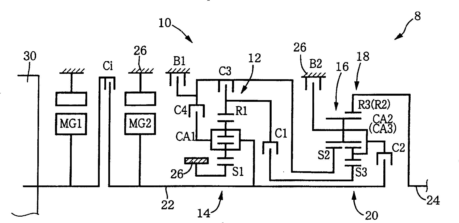
[0164] first reference Figure 1A is a schematic diagram illustrating the basic arrangement of a vehicle drive system 8 of a hybrid vehicle to which the principles of the present invention may be applied. The drive system 8 includes an automatic transmission 10 having a plurality of gear positions established by respective combinations of operating states (engagement and disengagement actions) of hydraulically operated friction coupling devices (described below). The drive system 8 also includes an engine 30 operable to generate vehicle driving force through combustion of fuel, a first electric motor MG1, and a second electric motor MG2. The drive system 8 is properly mounted on a front-engine rear-drive vehicle (FR vehicle) so that the axial direction of the engine 8 is parallel to the longitudinal or traveling direction of the vehicle, and so that the engine 8, the first electric motor MG1 and the second electric motor MG2, and The automatic transmissions 10 are arranged coa...


PUM


Abstract

A deceleration control apparatus for controlling a deceleration value of a vehicle, including a plurality of deceleration-value setting devices, a target-deceleration-value control portion operable to change a target deceleration value of the vehicle according to an operation of each of the deceleration-value setting devices, and a brake control portion operable to control a braking force to be applied to the vehicle, according to the target deceleration value changed by the target-deceleration-value control portion, wherein the target-deceleration-value control portion is operable to successively change the target deceleration value of the vehicle in response to successive operations of one and another of the plurality of deceleration-value setting devices such that the target deceleration value changed according to the operation of the above-indicated one deceleration-value setting device is subsequently changed according to the operation of the above-indicated another deceleration-value setting device.

Description

technical field [0001] The present invention generally relates to a control device for controlling a deceleration value of a vehicle, and more particularly, the present invention relates to a technique for easily setting a plurality of vehicle deceleration value setting devices. Background technique [0002] There is known a vehicle deceleration control device comprising (a) a target deceleration value control section operable to increase or decrease a target deceleration value of the vehicle in accordance with an operation of a deceleration value setting device, and (b ) A brake control section operable to control the braking force of the vehicle in accordance with the target deceleration value set by the deceleration value setting device. JP-2000-245016A discloses an example of such a vehicle deceleration control device, in which the shift lever has an "E" position and is operable from this "E" position to "Decel" for increasing the target deceleration value of the vehicle...

Claims


Application Information

Patent Timeline
IPC IPC(8): B60L7/10B60K6/48B60K6/547B60L15/20B60W10/04B60W10/08B60W10/10B60W10/11B60W10/115B60W20/00F02D29/00F02D29/02F02D29/06F16H59/48F16H61/02F16H61/68F16H61/684F16H61/686F16H63/50
CPCY02T10/6217Y02T10/70Y02T10/7258B60L2250/26B60L11/14B60L7/26B60L7/18B60L11/123B60L2250/24Y02T10/7077B60L50/16B60L50/61Y02T10/62Y02T10/7072Y02T10/72
Inventor 田端淳野崎和俊
Owner TOYOTA JIDOSHA KK
Why Eureka
Try Eureka