Air and gas supply structure of gas radiant furnace

An air supply and radiant furnace technology, applied in the field of gas radiant furnace, can solve the problems of reducing the heating efficiency of the heated body, uneven air velocity, uneven flame distribution, etc. The effect of flow speed

Inactive Publication Date: 2006-03-15
LG ELECTRONICS (TIANJIN) APPLIANCES CO LTD
View PDF0 Cites 1 Cited by
  • Summary
  • Abstract
  • Description
  • Claims
  • Application Information

AI Technical Summary

Problems solved by technology

[0013] In this way, the speed of the air flowing into the mixing tube 5 is not uniform and cannot be mixed well with the gas. Therefore, while the combustion stove 6 causes incomplete combustion, uneven and eccentric pressure is caused on the stove pad 7 during the combustion process. Flame distribution, reducing the heating efficiency of the heated body

Method used


Image

  • Air and gas supply structure of gas radiant furnace
  • Air and gas supply structure of gas radiant furnace
  • Air and gas supply structure of gas radiant furnace

Examples


Embodiment Construction

[0034] Next, the structure of the gas radiation furnace of the present invention will be described with reference to the accompanying drawings and examples.

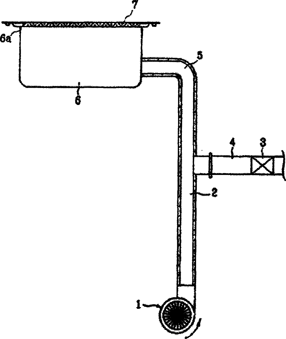
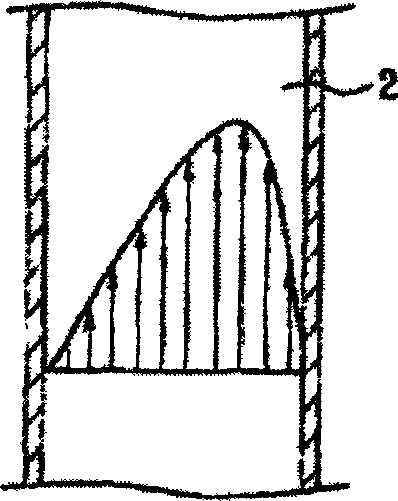
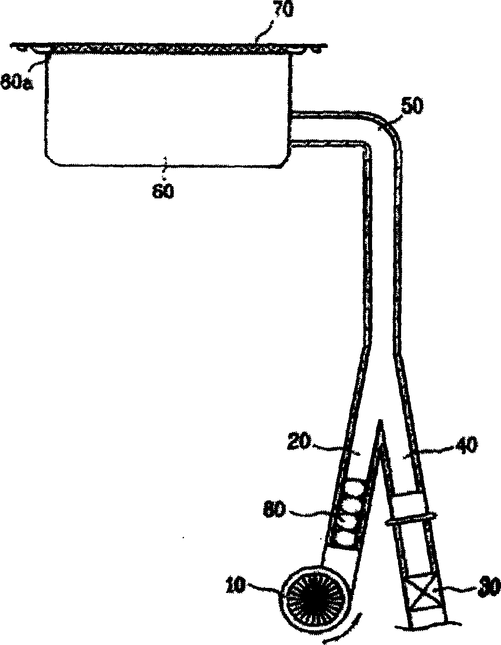
[0035] image 3 It is a brief structural sectional view of a gas radiation furnace in the present invention, Figure 4 yes image 3 Schematic diagram of the structure of the gas stirring device in Figure 5 yes image 3 The profile diagram of the air flow velocity distribution in the air supply pipe.

[0036] Such as image 3 and Figure 4 As shown, the air and gas supply structure of the gas radiant furnace according to the present invention includes the following structures, that is, the mixing tube 50, and the air and gas flow are mixed after they flow into the interior; the air supply tube 20, one side of which is connected to the mixing tube. Pipe 5, the other side is connected to air supply fan 10, so that the air flowing in through air supply fan 10 is supplied to the inside of mixing pipe 50; gas supply pip...


PUM


Abstract

An air and gas supply structure for the gas radiant furnace comprises a mixing tube, an air supply tube and a gas supply tube. The air supply tube and the gas supply tube are disposed axially along the mixing tube. A gas mixing device disposed in the air supply tube can make the air flowed into the tube have the uniform flow rate. The uniform flow rate of the air can minimize the flow resistance of the air and gas to reduce the flowing noise while mixing the air and gas fully and uniformly.

Description

technical field [0001] The present invention relates to a gas radiant furnace, in particular to an air supply pipe and a gas supply pipe for a gas radiant furnace and a gas supply structure. Background technique [0002] Generally speaking, the gas radiant furnace is a kind of heating equipment, that is, the mixed gas formed by the mixture of fuel and air will produce radiant body when burning, and the radiant body will generate radiant energy when heated, under the action of this radiant energy, the gas The radiant oven can heat and cook the object to be heated. [0003] Below, the structure of the gas radiation furnace under the prior art will be described in detail with reference to the accompanying drawings. [0004] figure 1 It is a schematic sectional view of a gas radiation furnace in the prior art, figure 2 yes figure 1 Cross-sectional view of the air flow velocity distribution inside the air supply pipe. [0005] Such as figure 1 As shown, the air and gas sup...

Claims


Application Information

Patent Timeline
Patent Type & Authority Applications(China)
IPC IPC(8): F23D14/62F23D14/02F23D14/34
Inventor 金英秀李大来郑大喜
Owner LG ELECTRONICS (TIANJIN) APPLIANCES CO LTD
Why Eureka
Try Eureka