Method and device for igniting detonator

A detonator and chip technology, used in fuzes, blasting tubes, weapon accessories, etc., can solve the problems of anti-static, anti-stray current and poor electromagnetic radiation resistance, and achieve high anti-electromagnetic radiation ability, strong environmental adaptability, and anti-miscellaneous radiation. The effect of dissipating current

Active Publication Date: 2006-03-22
GUIZHOU JIULIAN IND EXPLOSIVE MATERIALS DEV +1
View PDF0 Cites 12 Cited by
  • Summary
  • Abstract
  • Description
  • Claims
  • Application Information

AI Technical Summary

Problems solved by technology

However, the existing industrial electric detonator ignition and detonation devices can no longer meet the needs of use due to the relatively poor antistatic, anti-stray current, and anti-electromagnetic radiation capabilities.

Method used


Image

  • Method and device for igniting detonator
  • Method and device for igniting detonator

Examples


Embodiment Construction

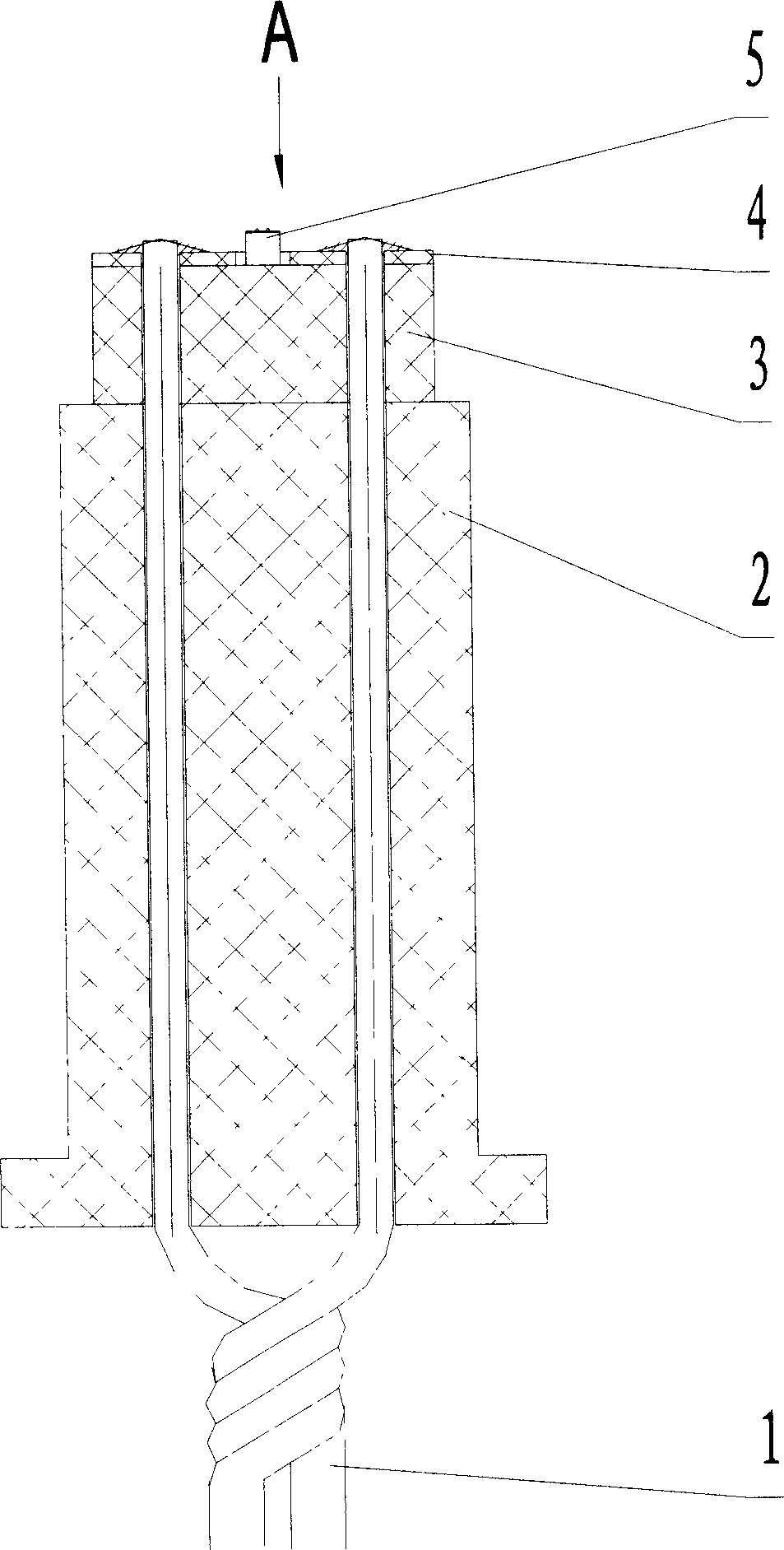
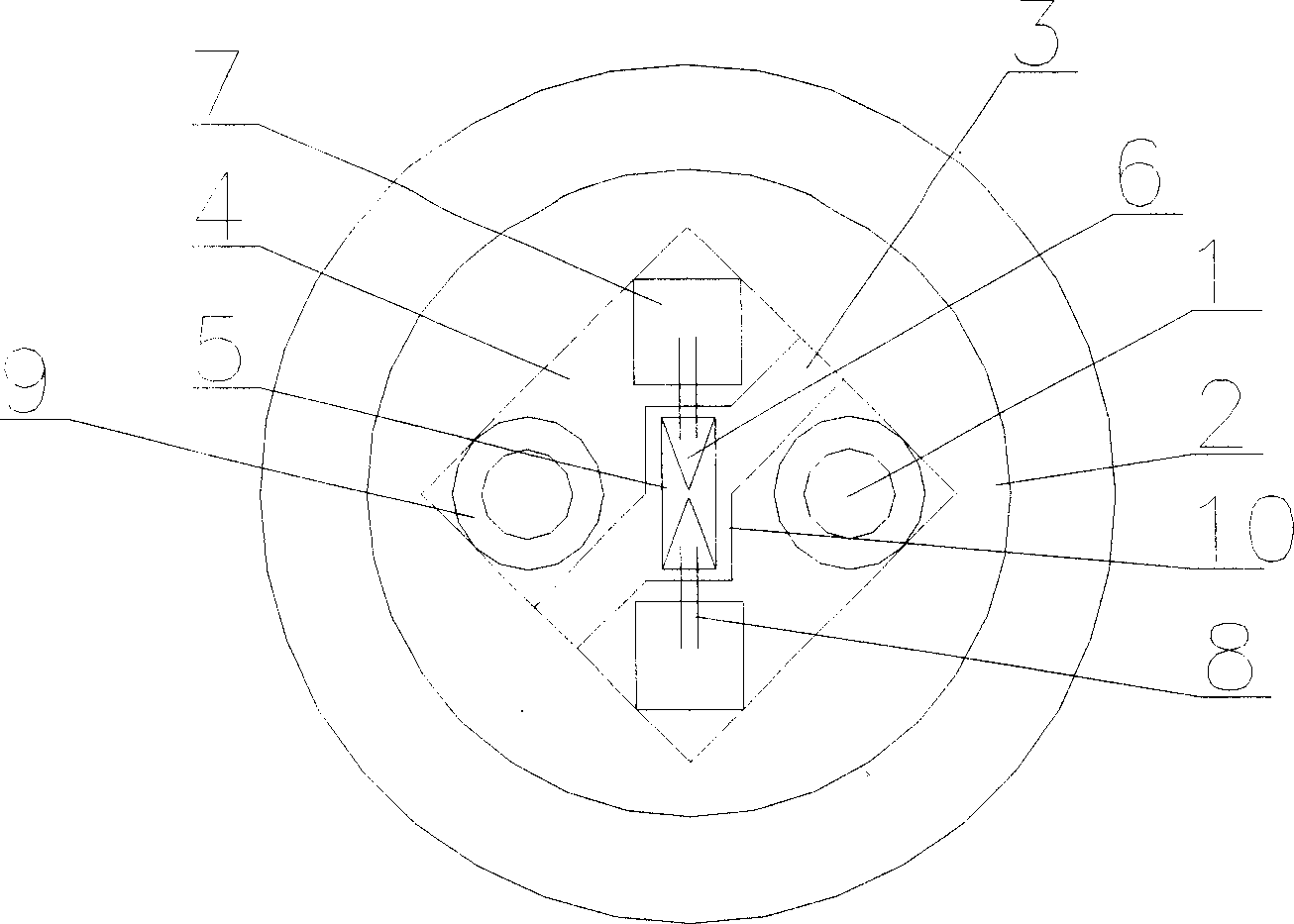
[0014] Embodiment of the present invention: when making the ignition and detonation device of electric detonator, adopt the semiconductor chip 5 made of polysilicon material sold on the market as the ignition detonation material of electric detonator, and use the detonation power source of the original electric detonator as the ignition source of this semiconductor chip Power supply, so that the current pulse of the power supply can act on the semiconductor material, so that when the electric detonator is detonated, the current pulse flows through the semiconductor material to heat it, and after the semiconductor material is vaporized, an explosion is generated to form a high temperature and high pressure plasma impact body , the heat energy generated by the plasma and the ejected plasma act on the detonating particles in the detonator to ignite the explosive in the detonator, thereby detonating the detonator.

[0015] When specifically manufacturing the ignition and detonation...


PUM


Abstract

The present invention discloses method and device of igniting detonator. Semiconductor chip is used as the igniting material of detonator and is heated with current pulse flowing through to vaporize the semiconductor chip material to form high temperature and high pressure plasma impact body. The plasma and its heat energy act on the detonating explosive grain to ignite the detonator. The present invention has greatly raised safety performance, excellent capacity of resisting static electricity, stray current and electromagnetic radiation, no environment, simple operation, short acting time and other advantages. The present invention may be used to ignite several kinds of explosive material.

Description

Technical field: [0001] The invention relates to a method and a device for igniting and detonating a detonator, belonging to the technical field of detonator ignition and detonation. Background technique: [0002] At present, the ignition part of the ignition and detonation mechanism of the industrial electric detonator used in the prior art is mainly composed of electric heating bridge wires and chemicals. During the production process of bridge wires and chemicals, the resistance and the sensitivity of chemicals are caused by raw materials, production technology and other reasons. The consistency is poor, and the medicine is easy to malfunction under the action of high static electricity and electromagnetic radiation, resulting in unsafe problems during production, storage, transportation and use. With the rapid development of modern society, the radiation and interference of static electricity, stray current, and electromagnetic waves generated by the environment are incr...

Claims


Application Information

Patent Timeline
Patent Type & Authority Applications(China)
IPC IPC(8): F42C19/12F42B3/10
CPCF42B3/12
Inventor 占必文费三国聂煜杨黎明刘刚施志贵
Owner GUIZHOU JIULIAN IND EXPLOSIVE MATERIALS DEV
Why Eureka
Try Eureka