

Control parameter setting method for control circuit in measurement control system and measuring instrument
A technology for controlling parameters and controlling circuits, applied in the direction of amplification control, gain control, electrical components, etc., can solve the problems of small frequency characteristics of the measurement control system and destruction of measurement stability, and achieve high steady-state characteristics and stability , highly stable effect
Inactive Publication Date: 2010-08-25
MITUTOYO CORP
View PDF1 Cites 0 Cited by
- Summary
- Abstract
- Description
- Claims
- Application Information
AI Technical Summary
Problems solved by technology
Therefore, according to the above-mentioned gain setting method of Document 1, the frequency characteristic of the measurement control system is adjusted to the maximum by setting the optimum gain for the control circuit. However, at least one of the measurement device and the object to be measured If the measurement device or object to be measured is replaced with a different one, the frequency characteristic of the measurement control system will be reduced due to deterioration, and the stability of the measurement may be impaired.
Method used
View moreImage
Smart ImageViewing Examples


Examples
Embodiment Construction
Login to View More PUM
 Abstract
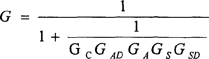
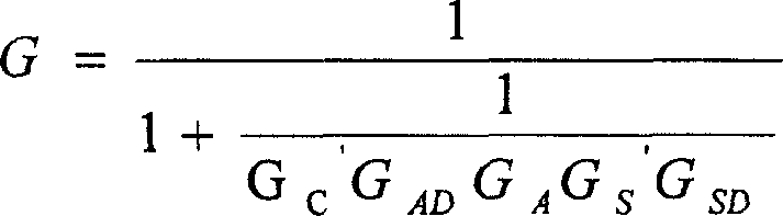
The invention provides a control parameter setting method for control circuit in measurement control system and measuring instrument. N pieces of gains G i are sequentially and temporarily set in a control circuit (23), and a stylus (131) is brought in contact with a workpiece (W) for conducting a temporary measurement. At this time, a sensor detection signal output from a sensor detection circuit (21) is filtered by a filter (31) to take out only a frequency component corresponding to a frequency of hunting generated in a closed loop (L) including the control circuit (23). Gains G j that do not generate hunting in the closed loop (L) are extracted, and the largest gain G j is set in the control circuit (23) in view of enhancement in responsivity etc. of the measurement. Alternatively, bypressing the stylus (131) into the workpiece (W), a displacement signal indicating a pressing amount and a sensor signal output from a sensor (13) are measured in accordance with a measurement load applied to the stylus (131) to calculate a gain G s ' of the sensor (13) based on the two signals. By compensating the gain of the control circuit in accordance with the gain G s '.
Description
technical field The invention relates to a control parameter setting method and a measuring device of a control circuit of a measurement control system. Background technique As the control parameters of the control circuit, there are gain, phase compensation frequency, etc., and the following method is known as the gain setting method of the control circuit of the measurement control system in the past, and the method includes: obtaining the data required for gain setting The data obtaining step, the judging step of judging the gain most suitable for measurement based on the data, and the setting step of setting the gain of the control circuit to the gain judged to be optimum (for example, refer to Patent Document 1). Here, the optimum gain of the control circuit means a gain that can prevent the measurement control system from becoming a self-oscillating state, realize a stable measurement state, and enable rapid measurement. The optimum gain can be judged by various meth...
Claims
Login to View More Application Information
Patent Timeline
 IPC IPC(8): H03G3/00H03G3/20
Inventor斋藤章宪日高和彦
OwnerMITUTOYO CORP