Refrigeration cycle apparatus
A refrigeration cycle and equipment technology, applied in the field of refrigeration cycle equipment, can solve the problems of high cost and high price
- Summary
- Abstract
- Description
- Claims
- Application Information
AI Technical Summary
Problems solved by technology
Method used
Image
Examples
no. 1 example
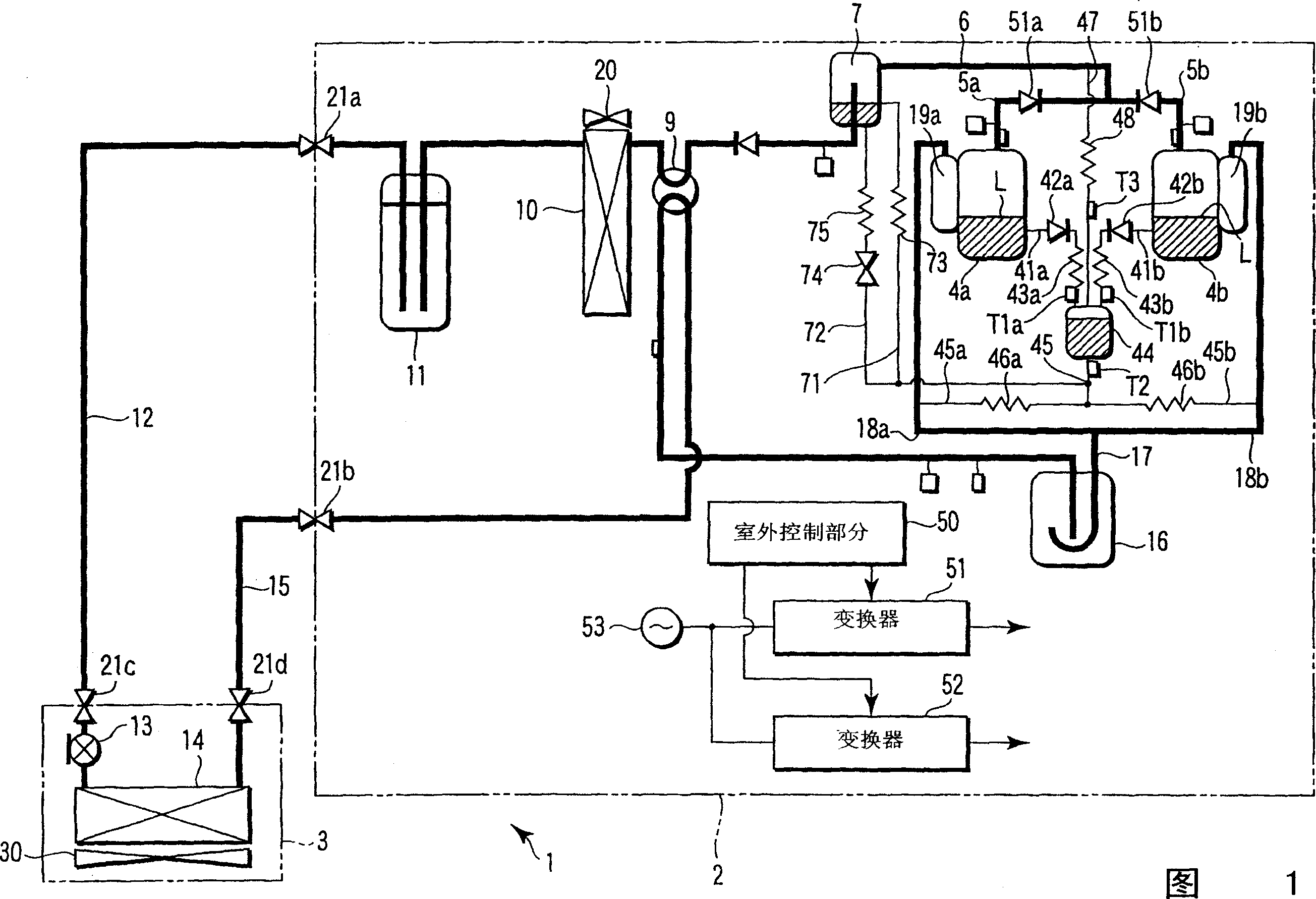
[0021] The refrigeration cycle apparatus 1 includes an air conditioner composed of an outdoor unit 2 and an indoor unit 3 . The outdoor unit 2 includes compressors 4a, 4b, oil separator 7, four-way valve 9, outdoor heat exchanger 10, liquid container 11, accumulator 16, outdoor fan 20, outdoor control section 50, inverters 51, 52, and the like. The indoor unit 3 includes an electronic expansion valve 13, an indoor heat exchanger 14, an indoor fan 30, an indoor control section (not shown), and the like. The outdoor unit 2 and the indoor unit 3 are connected by a liquid pipe 12 and a gas pipe 15.
[0022] The outdoor control section 50 controls the operation of the outdoor unit 2 . The converters 51 and 52 rectify the voltage of the commercial AC power source 53, and convert the rectified voltage into an AC voltage of a frequency corresponding to the structure of the outdoor control section 50 and output it. Compressors 4 a and 4 b are of the variable capacity type and are dri...
no. 3 example
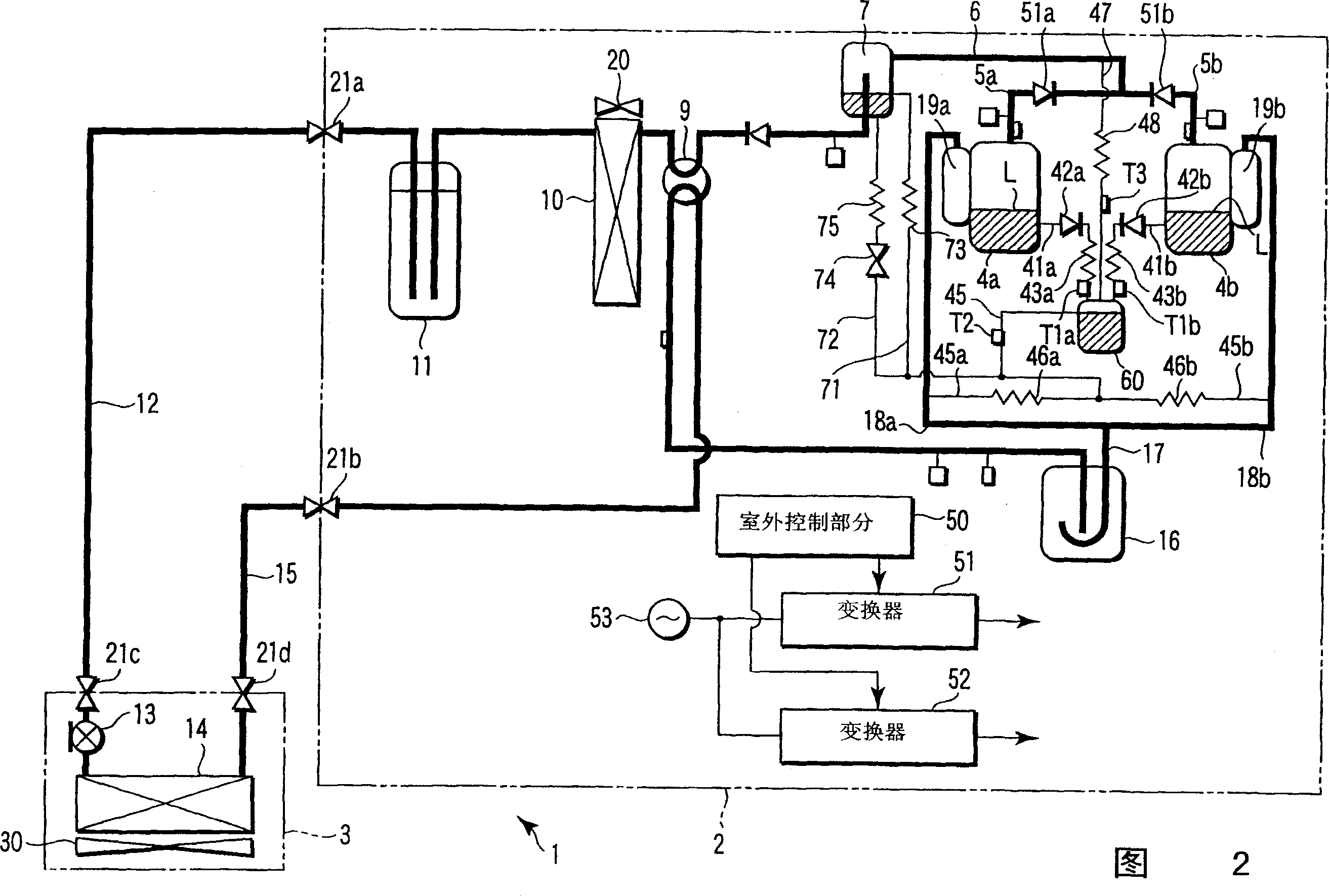
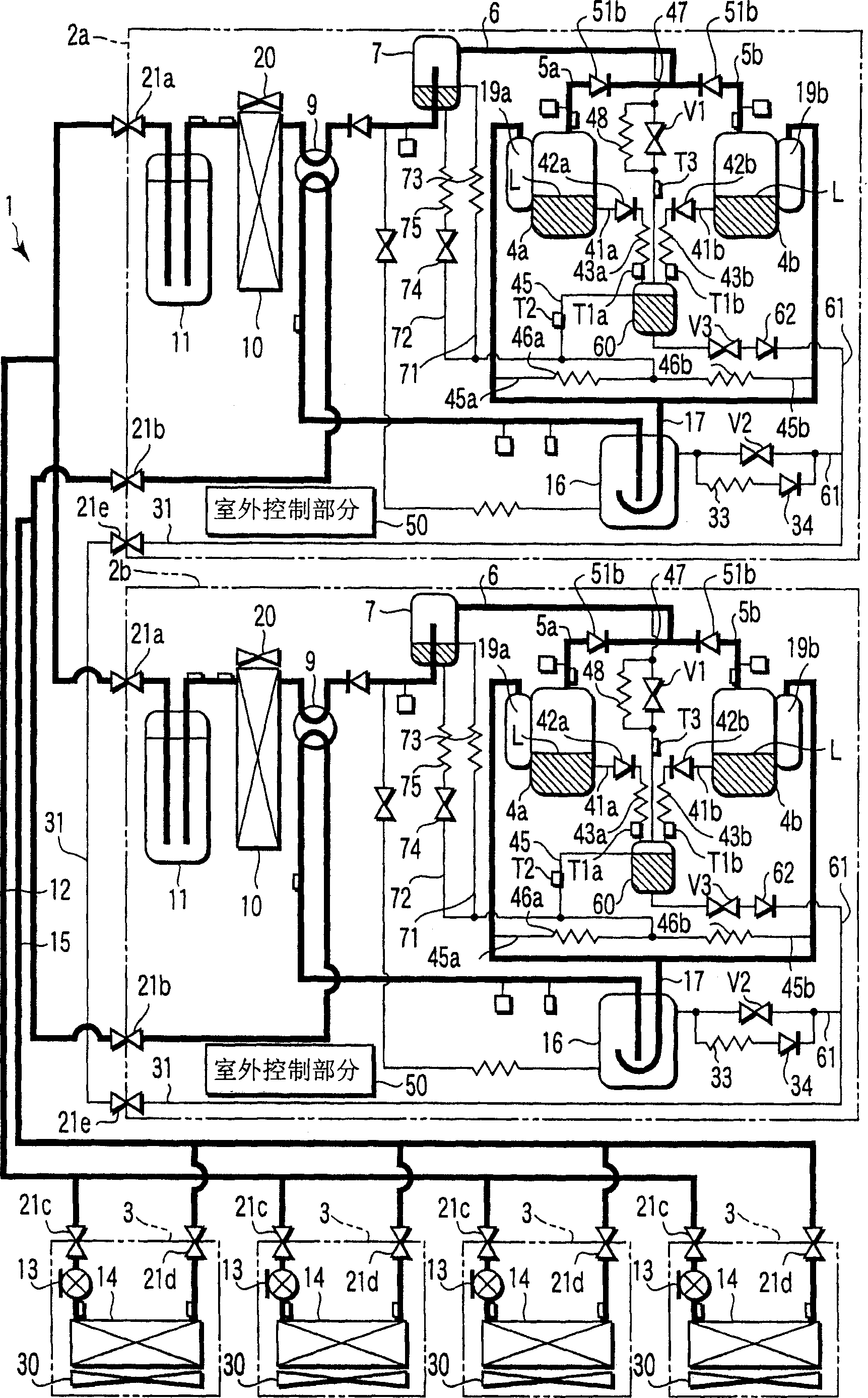
[0061] Such as image 3 As shown, the air conditioner includes a plurality of outdoor units 2 a, 2 b and a plurality of indoor units 3 . The outdoor unit 2a has the same structure as the outdoor unit 2 of the second embodiment and has compressors 4a, 4b. The outdoor unit 2b has the same structure as the outdoor unit 2 of the second embodiment and has compressors 4a, 4b.
[0062] Parallel to the capillary 48 in the bypass pipe 47, a first on / off valve V1 is connected to each outdoor unit 2a, 2b.
[0063] For each outdoor unit 2a, 2b, a third oil balance pipe 61 is connected from the bottom of the oil tank 60 to the low pressure side pipe 17. Second and third on / off valves V2 and V3 are provided at the oil balance pipe 61 . Also, a series circuit of the capillary 33 and the one-way valve 34 is connected in parallel with the on / off valve V2 in the oil balance pipe 61 .
[0064] The balance pipe 31 is connected between those interconnections at a position between the on / off val...
PUM
 Abstract
Description
Claims
Application Information
 - R&D Engineer
- R&D Manager
- IP Professional
- Industry Leading Data Capabilities
- Powerful AI technology
- Patent DNA Extraction
Browse by: Latest US Patents, China's latest patents, Technical Efficacy Thesaurus, Application Domain, Technology Topic, Popular Technical Reports.
© 2024 PatSnap. All rights reserved.Legal|Privacy policy|Modern Slavery Act Transparency Statement|Sitemap|About US| Contact US: help@patsnap.com


