Supercharge Your Innovation With Domain-Expert AI Agents!

Digital phase modulator for a fiber-optic device

A technology of digital phase modulation and phase modulator, which is applied in the pressure field, can solve the problems of limited thermal stability and high technical cost, and achieve the effect of reducing problems

Inactive Publication Date: 2006-03-22
LITEF
View PDF1 Cites 3 Cited by
  • Summary
  • Abstract
  • Description
  • Claims
  • Application Information

AI Technical Summary

Problems solved by technology

The solution described in said document allows for an increase in resolution, but is technically expensive, due on the one hand to the use of correction tables and, on the other hand, in particular also due to the need to use a D / A converter with a driver, and The analog output value of this converter is only limited thermally stable

Method used


Image

  • Digital phase modulator for a fiber-optic device
  • Digital phase modulator for a fiber-optic device
  • Digital phase modulator for a fiber-optic device

Examples


Embodiment Construction

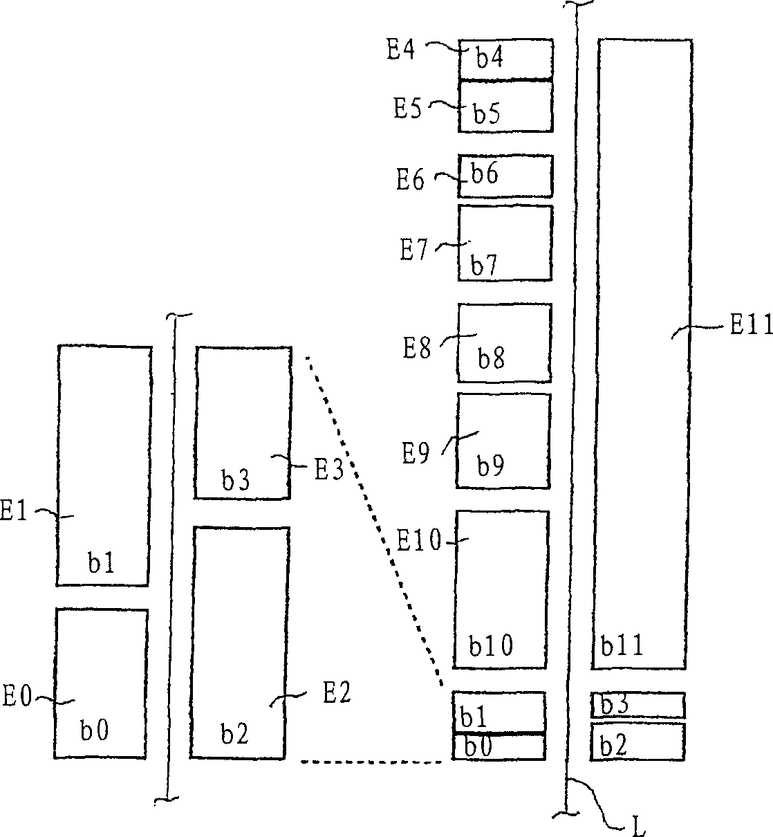
[0040] figure 1 An exemplary embodiment of a digital phase modulator with increased resolution according to the invention is shown in an enlarged schematic view. The phase modulator includes 12 electrodes with different lengths and weights, denoted by E0, E1, . . . , E10, E11. In order to show an important feature of the present invention, namely the non-binary arrangement of the low significant bit electrodes E0 to E3, these electrodes are placed in figure 1Zoom in to the left. As shown, the electrodes E0, E1 and E4 to E10 arranged on the left side of the optical waveguide L occupy the value positions b0, b1 and b4 to b10, while the electrodes E2, E3 and E11 arranged on the right side of the optical waveguide L occupy the value positions b2, b3 and b11.

[0041] Thus, in figure 1 The embodiment of the present invention gives the so-called "8+4 configuration", in which the upper 8 electrodes E4 to E11 are binary weighted and constitute a first electrode group called "coars...


PUM


Abstract

A digital phase modulator for a fiber-optic signal transmission or measuring device that has a predetermined total number m of electrodes (E0 to E11) of varying length that are disposed in parallel and at both sides of a light guiding path (L) in or on an optical substrate. The aim of the invention is to substantially increase the resolution of such a digital phase modulator. This aim is achieved by the method according to the invention and the corresponding system of electrodes which are based on the idea of dividing the electrodes up into two groups. A first group n of electrodes (E4 to E11) represents a macro-modulator having binary weighted and higher order electrodes with a length ratio of bn+1: bn = 2, whose longest electrode (E11) corresponds to the sum of lengths of all remaining electrodes of the overall modulator, while a second smaller group of n0 not-binary weighted and low order electrodes (E0 to E3) represents a micro-modulator. The smallest initial values are no longer produced by controlling individual electrodes of the micro-modulator but by calculating the difference between two larger electrodes each. Despite the comparatively short length of the phase modulator that would allow only for a resolution of 9 bits (electrode ratio of approximately 1:2-9) for technological reasons, the inventive subdivision into two different modulator concepts allows for a resolution in a value range of approximately 12 bits. The particular advantage is that it is no longer necessary to use a correction chart and if said chart, if available, fails, an emergency service with reduced resolution can be provided.

Description

technical field [0001] The invention relates to a method of increasing the resolution of a digital phase modulator for optical fiber signal transmission or measuring equipment, the phase modulator having a predetermined total number of electrodes of different lengths, which electrodes are parallel to the light-guiding path and at both ends of the light-guiding path Sideways are arranged in or on the light base, wherein the electrodes on both sides of the light guide path are applied with preferably the same control voltage, so that multiple phase values ​​are set within a predetermined value range by alternating control selection electrode combinations. [0002] For control, the electrodes of the phase modulator are preferably supplied with the same potential, which, depending on the position of the electrodes relative to the light-conducting path, shifts the phase of the light at the output of the modulator positively or negatively. The electrodes are also referred to below s...

Claims


Application Information

Patent Timeline
Patent Type & Authority Applications(China)
IPC IPC(8): G01C19/72G02F1/01G02F1/03
CPCG02F2203/50G02F1/0115G01C19/726G02F1/0316G02F2201/122
Inventor 斯文·沃伊特冈特·斯帕林格阿方斯·纽泽拉
Owner LITEF
Features
  • R&D
  • Intellectual Property
  • Life Sciences
  • Materials
  • Tech Scout
  • Unparalleled Data Quality
  • Higher Quality Content
  • 60% Fewer Hallucinations
Learn More