Air cooled steam exhaustor with built-in oxygen remover

A built-in, steam-exhausting technology, applied in engine components, machines/engines, mechanical equipment, etc., can solve problems such as occupying plant space and poor deoxidization effect.

Active Publication Date: 2006-03-29
HARBIN TURBINE
View PDF0 Cites 6 Cited by
  • Summary
  • Abstract
  • Description
  • Claims
  • Application Information

AI Technical Summary

Problems solved by technology

[0002] The exhaust device of the existing air-cooled turbogenerator set, the condensate water deoxygenation device is independently arranged outside the exhaust device, which not only occupies a large amount of power plant workshop space, but also has a poor deoxygenation effect

Method used


Image

  • Air cooled steam exhaustor with built-in oxygen remover
  • Air cooled steam exhaustor with built-in oxygen remover

Examples


specific Embodiment approach 1

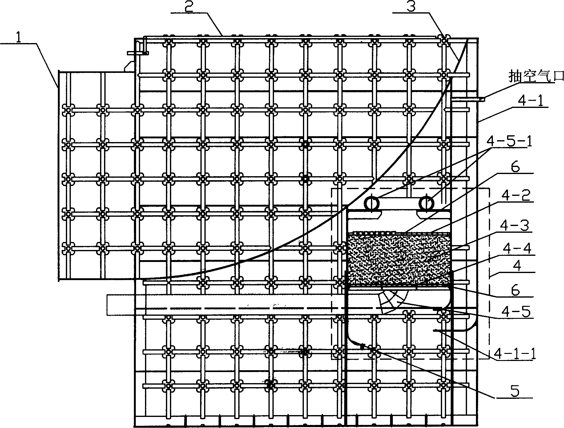
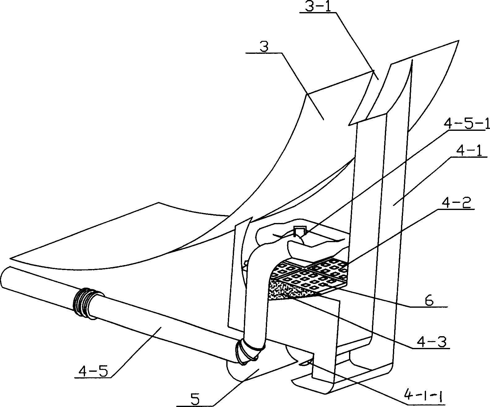
[0005] Specific implementation mode one: refer to figure 1 , figure 2 , this embodiment is an air-cooled steam exhaust device with a built-in oxygen removal device, which includes a steam exhaust device 1, and a condensed water replenishment water spray pipe 2 and a deflector 3 are arranged in the steam exhaust device 1. The steam device 1 is also provided with an oxygen removal device 4, which includes a heating steam channel 4-1, an upper shower net 4-2, a packing layer 4-3, a lower shower net 4-4 and condensed water The pipeline 4-5, the upper shower net 4-2 and the lower shower net 4-4 are provided with holes 6 for water supply and gas to pass through, and the packing layer 4-3 is arranged on the upper shower net 4-2 and the lower shower net 4-2. Between the sprinkler nets 4-4, the spray outlet 4-5-1 of the condensed water pipeline 4-5 is arranged above the upper sprinkler net 4-2, and the air jet outlet 4-1-1 of the heating steam channel 4-1 It is arranged below the lo...

specific Embodiment approach 2

[0007] Specific implementation mode two: refer to figure 2 , the upper end of the deflector 3 is provided with an opening 3-1, and the upper end of the heating steam channel 4-1 is arranged below the opening 3-1, and the opening on the deflector 3 can allow a sufficient amount of steam to enter the heating steam Passage 4-1; a steam baffle 5 is provided at the front and bottom of the air jet 4-1-1 of the heating steam passage 4-1, and the steam baffle can ensure that the steam coming out of the heating steam passage 4-1 can pass through the lower The water shower net 4-4 is sprayed into the filler layer 4-3.


PUM


Abstract

The invention includes a exhaust device, a sparge pipeline, a deflector and a deaerator set in the exhaust device. The deaerator comprises a heating steam passage, a upper sprinkling screen, a lower sprinkling screen, a stuffing layer disposed between the upper sprinkling screen and the lower sprinkling screen and a condensation water pipeline. The water jet of the condensation water pipeline is set above the upper sprinkling screen. The air jet of the heating steam passage is set below the lower sprinkling screen.

Description

technical field [0001] The invention relates to a steam exhaust device. Background technique [0002] In the existing steam exhaust device for air-cooled turbo-generator set, the condensed water deoxygenation device is independently arranged outside the exhaust device, which not only occupies a large amount of power plant workshop space, but also has poor oxygen removal effect. Contents of the invention [0003] Aiming at the disadvantages of the existing oxygen removal device being arranged outside the steam exhaust device, which takes up a large space and has a poor oxygen removal effect, the present invention provides a built-in oxygen removal device that can save space and have a good oxygen removal effect. An air-cooled steam exhaust device for an oxygen plant, which includes a steam exhaust device, in which a condensed water replenishment water spray pipe and a deflector are arranged, and a deoxygenation device is also provided in the steam exhaust device, and the de...

Claims


Application Information

Patent Timeline
Patent Type & Authority Applications(China)
IPC IPC(8): F01D25/30
Inventor 林秋宇武君杨镇海陈静涛刘克为
Owner HARBIN TURBINE
Why Eureka
Try Eureka