Hydraulic reciprocating pump

A reciprocating pump and hydraulic technology, applied in the direction of pumps, piston pumps, liquid displacement machinery, etc., can solve the problems of high cost, complex structure of reciprocating pumps, and restrictions on popularization and application

Inactive Publication Date: 2006-03-29
NANJING QUANZHANG HYDRAULIC SCI & TECH
View PDF0 Cites 12 Cited by
  • Summary
  • Abstract
  • Description
  • Claims
  • Application Information

AI Technical Summary

Problems solved by technology

However, the reciprocating pump with electric motor or steam engine as the driving force has complex structure and high cost, which limits its further popularization and application.

Method used


Image

  • Hydraulic reciprocating pump

Examples


Embodiment Construction

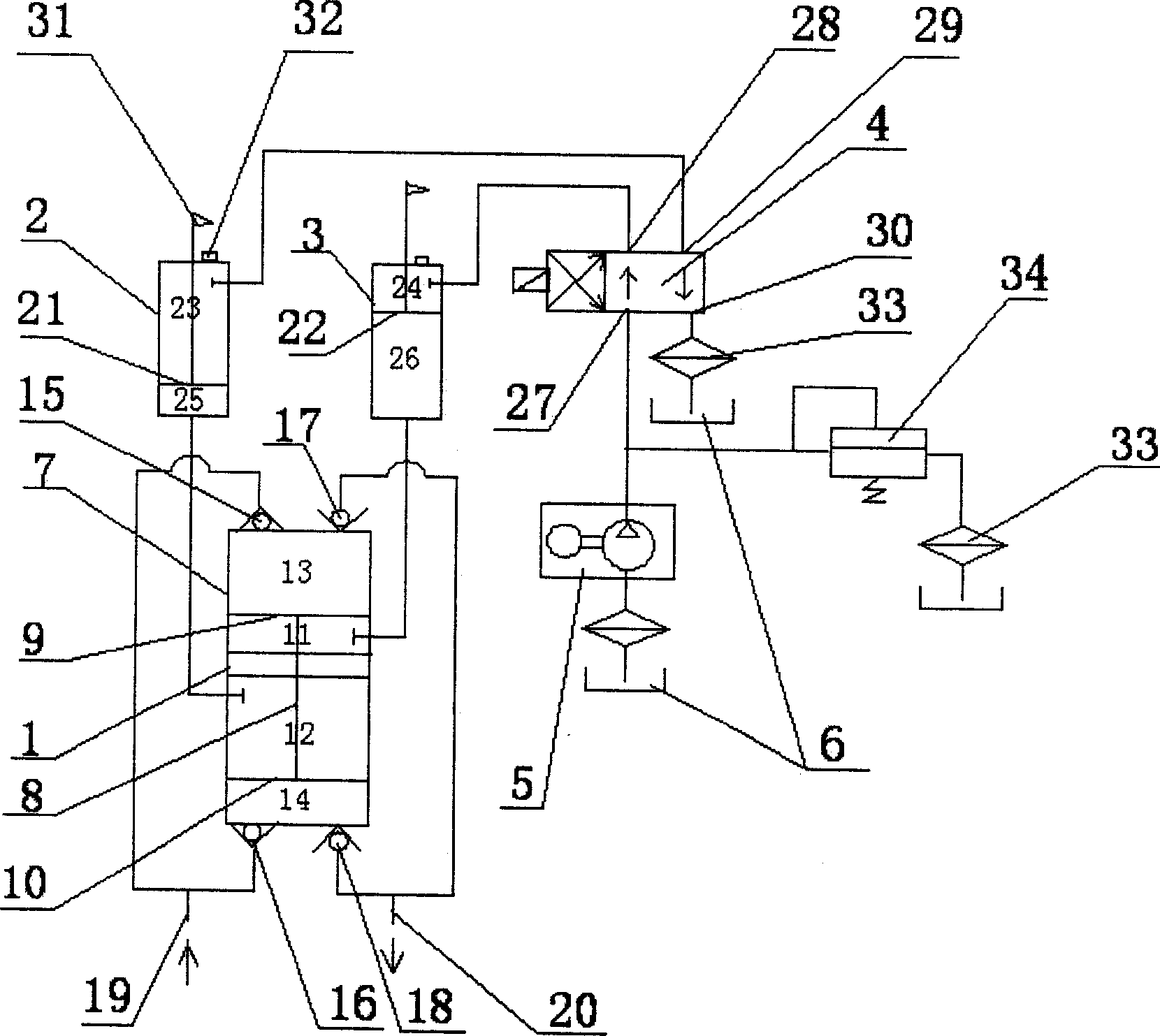
[0015] Such as figure 1 As shown, the hydraulic reciprocating pump of the present invention includes a reciprocating pump 1, two power cylinders 2, 3, a reversing valve 4, a pump motor unit 5 and an oil tank 6 with hydraulic oil; wherein:

[0016] The reciprocating pump 1 includes a pump body 7 with two connected chambers and a piston assembly. The piston assembly is composed of a piston rod 8 and two pistons 9, 10 installed at both ends of the piston rod 8. The two pistons 9, 10 are respectively Set in the two chambers of the pump body 7, and divide the chambers into hydraulic chambers 11, 12 and working chambers 13, 14, the working chambers 13, 14 are respectively connected with liquid inlet check valves 15, 16 and liquid outlet One-way valves 17, 18, wherein the liquid inlet one-way valves 15, 16 are connected to the liquid inlet pipe 19, and the liquid outlet one-way valves 17, 18 are connected to the liquid outlet pipe 20, and the reciprocating pump 1 can be a vertical or...


PUM


Abstract

There is disposed a hydraulic reciprocating pump which comprises a reciprocating pump, two power cylinders, a reversing valve, pump electric unit and fuel tank with hydraulic oil. The chamber is separated to a hydraulic chamber and a working chamber by the piston in the reciprocating pump. The working chamber is connected into the one-way valve. The liquid is poured fully into the non-piston chamber of the power cylinder which is connected with the hydraulic chamber of the pump body via the pipeline. A control mechanism of the reversing valve is disposed on the power cylinder. The oil inlet of the reversing valve is connected with the pump electric unit and fuel tank successively by the pipeline. Two oil outlets are connected to the chamber with pistons of the power cylinder separately by the pipeline. The backflow port is connected with the fuel tank by the pipeline.

Description

1. Technical field [0001] The invention relates to a pump, in particular to a hydraulic reciprocating pump using liquid to transmit power. 2. Background technology [0002] A pump is a mechanical device that transports or pressurizes a liquid. It transmits the mechanical energy of the prime mover or other external energy to the liquid, so that the kinetic energy of the liquid is increased and transported along the pipeline. Pumps are mainly used to transport liquids including water, oil, acid and alkali, emulsions, suspoemulsions and liquid metals, etc., and can also transport liquids, gas mixtures and liquids containing suspended solids. According to the working principle, pumps can be divided into positive displacement pumps, dynamic pumps and other types of pumps, such as jet pumps, water hammer pumps, electromagnetic pumps, and gas lift pumps. [0003] The positive displacement pump relies on the working element to reciprocate or rotate in the pump cylinder, so that th...

Claims


Application Information

Patent Timeline
Patent Type & Authority Applications(China)
IPC IPC(8): F04B9/105F04B35/02
CPCF04B9/113
Inventor 吕权王全章石晶
Owner NANJING QUANZHANG HYDRAULIC SCI & TECH
Why Eureka
Try Eureka