Direct current power supply apparatus and control method for the same, and a compressor drive apparatus

A technology of DC power supply and driving device, which is applied to the conversion device of output power, the conversion of irreversible AC power input to DC power output, electrical components, etc. problems such as high cost and high cost, to achieve the effect of reducing high-order harmonic current, reducing loss and noise, and preventing damage

Inactive Publication Date: 2006-03-29
PANASONIC CORP
View PDF1 Cites 23 Cited by
  • Summary
  • Abstract
  • Description
  • Claims
  • Application Information

AI Technical Summary

Problems solved by technology

[0008] However, in the structure of the above-mentioned existing DC power supply device, there are many switching elements for converting AC to DC, and its control is also very complicated.
In addition, since the reactor used must also be a device with good high-frequency performance, there is a problem of high cost
In addition, since the switching elements are driven with harmonics of several kHz to tens of kHz, the loss of switching elements, high-speed diodes, reactors, etc. is large, and there is a problem that the generation level of high-frequency noise is high.

Method used


Image

  • Direct current power supply apparatus and control method for the same, and a compressor drive apparatus
  • Direct current power supply apparatus and control method for the same, and a compressor drive apparatus
  • Direct current power supply apparatus and control method for the same, and a compressor drive apparatus

Examples


no. 1 approach

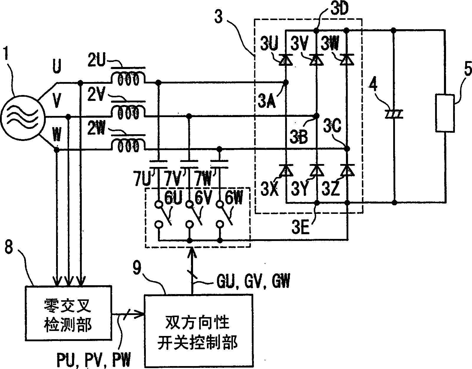
[0057] figure 1 It is a block diagram of the DC power supply device of the first embodiment of the present invention.

[0058] exist figure 1 Among them, each phase of U, V, and W of the three-phase AC power supply 1 is connected to the bridge rectifier circuit 3 composed of diodes 3U, 3V, 3W, 3X, 3Y, and 3Z through each reactor 2U, 2V, and 2W. Each AC input terminal 3A, 3B, 3C. The electrolytic capacitor 4 is connected between the positive DC output terminal 3D and the negative DC output terminal 3E of the bridge rectifier circuit 3 . Load 5 is connected in parallel with electrolytic capacitor 4 . Connect one end of each bidirectional switch 6U, 6V, 6W to the negative DC output end 3E of the bridge rectifier circuit 3, and connect their other ends to 7U, 7V, 7W respectively.

[0059] The other terminals of these capacitors 7U, 7V, and 7W are connected to AC input terminals 3A, 3B, and 3C of the rectifier circuit 3, respectively. In addition, the zero-cross detection un...

no. 2 approach

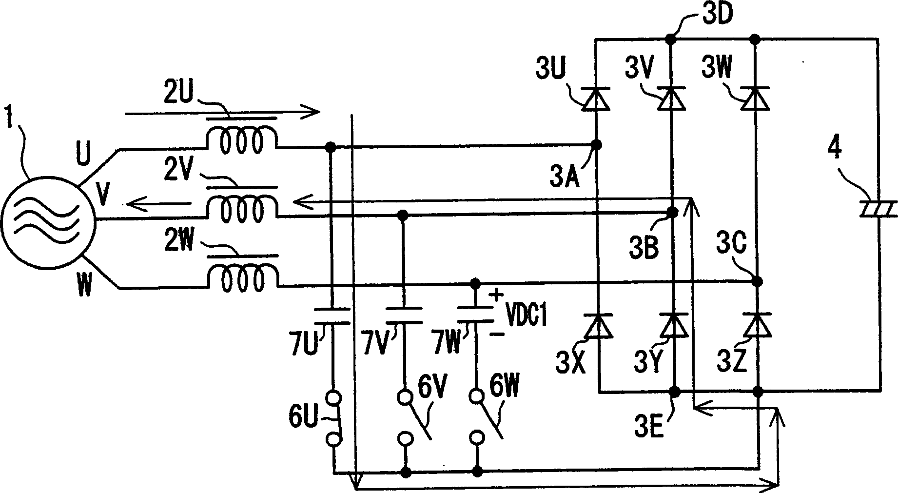
[0091] Figure 12 It is a block diagram of a DC power supply device according to a second embodiment of the present invention.

[0092] Figure 12 With respect to the block diagram of the DC power supply device of the first embodiment, the arrangement of capacitors 7U, 7V, and 7W is replaced by bidirectional switches 6U, 6V, and 6W, respectively, and a single capacitor 28 is integrated.

[0093] In the second embodiment, with respect to the first embodiment, the control and timing of the turn-on operation of each bidirectional switch 6U, 6V, 6W, and the flow through each bidirectional switch 6U, 6V, 6W and the bridge The current of the type DC circuit 3 is the same, and the improvement of the input power factor and the reduction effect of the high-order harmonic are also equivalent. The difference is that all the currents flowing through the capacitors 7U, 7V, and 7W in the first embodiment are configured to flow through the capacitor 28, and the phase in which the charging cu...

no. 3 approach

[0099] Figure 14 It is a block diagram of a DC power output device according to a third embodiment of the present invention.

[0100] Figure 14 compared to figure 1 The block diagram of the DC power supply device according to the first embodiment includes a DC voltage detection unit 21 for detecting the DC output voltage across the electrolytic capacitor 4, and a voltage abnormality detection unit 51 for detecting abnormalities in the detected DC voltage value.

[0101] The normal operation of the third embodiment is the same as that of the first embodiment. The bidirectional switches 6U, 6V, and 6W are controlled by the bidirectional switch control unit 9, and the input power factor is improved and the harmonic current is reduced. At the same time, DC power is supplied to the load 5 .

[0102] Here, abnormal rise and fall of the DC output voltage may be caused by a sudden change of the load 5 or a malfunction of the bidirectional switch control unit 9 . The difference ...


PUM


Abstract

The present invention provides a DC power supply apparatus and a compressor driving apparatus utilizing the DC power supply apparatus, the DC power supply apparatus includes; a three-phase AC power supply, a reactor, a bridge type rectifying circuit, a electrolytic capacitor, a double-direction switch, a capacitor, a phase detection unit of the specified phase for detecting each phase voltage, a controller of double-direction switch, the two-way switches are turned on / off every half cycle of each phase voltage of the three-phase AC supply to repeatedly and alternately charge and discharge the capacitors through the reactors, thereby reducing high frequency current components and improving the input power factor. Thus, a DC power supply apparatus reduces high frequency current and improves the input power factor by a simple circuit arragement.

Description

technical field [0001] The present invention relates to a DC power supply device, a control method, and a compressor using the DC power supply device, which convert a three-phase AC power supply into a DC power supply and reduce the high-order harmonic current flowing through the three-phase AC power supply to improve the input power factor. drive unit. Background technique [0002] In the past, in the DC power supply device that converts the three-phase AC power supply to DC, in order to improve the harmonics and power factor, many methods have been made to convert the current of the three-phase AC power supply to DC while keeping the current of the three-phase AC power supply in a sinusoidal shape. Various combinations. In particular, a method is adopted in which the switching element is driven in the range of several kHz to several tens of kHz, the current flowing through the switching element is controlled at high speed, and the target reference sinusoidal waveform is f...

Claims


Application Information

Patent Timeline
Patent Type & Authority Applications(China)
IPC IPC(8): H02M7/12H02M1/12
CPCH02M1/12Y02B70/126H02M1/4216Y02B70/10
Inventor 武田芳彦前田志朗
Owner PANASONIC CORP
Why Eureka
Try Eureka