
Carbon fiber friction material

A friction material and friction surface technology, applied in friction linings, textiles, mechanical equipment, etc., to solve problems such as blocking the flow of cooling fluids

Inactive Publication Date: 2006-03-29
BALLARD MATERIAL PRODS
View PDF1 Cites 8 Cited by
  • Summary
  • Abstract
  • Description
  • Claims
  • Application Information

AI Technical Summary

Problems solved by technology

However, pyrolytic carbon fabrics often impede the flow of cooling fluid

Method used


Image

  • Carbon fiber friction material
  • Carbon fiber friction material
  • Carbon fiber friction material

Examples


example

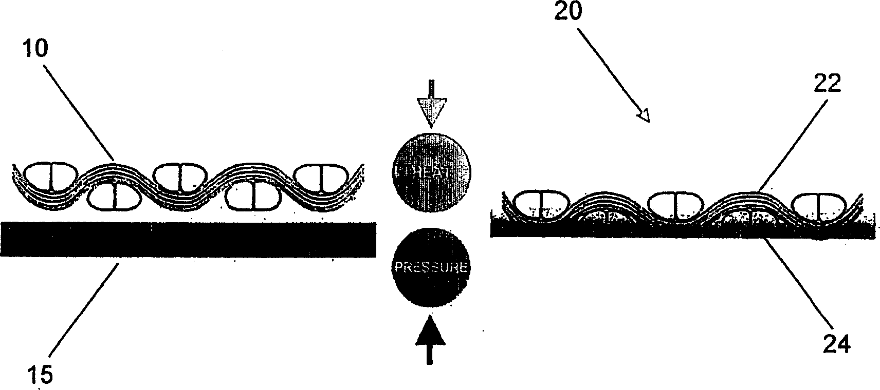
[0031] Place three plies of 7781 fiberglass woven cloth impregnated with epoxy resin (supplied by Fibercote Industries, Connecticut, USA) on the aluminum liner, and place a carbon woven cloth ply cpw-006 (Massachusetts, USA) BallardMateriad Products, Inc.). Cover the fabric layups with a vacuum bagging material and seal the liner with a vacuum sealing tape. A valve is inserted into the vacuum bag to apply vacuum during the curing process. Place the liner in the oven and apply vacuum to bring the apparatus to a pressure of 28-30 inches of mercury (Hg) (710-760 mm Hg). After achieving this vacuum, the apparatus was heated to 180°F (80°C) at a rate of 3-5°F per minute (2-3°C / min). After 30 minutes, the apparatus was reheated to 325°F (160°C) at the same ramp rate. After an additional 30 minutes at 325°F, the unit was allowed to cool to room temperature in vacuo overnight. The composite material is then removed from the liner. One side of the composite was surface-treated wit...


PUM


Abstract

A carbon friction material, preferably a woven carbon friction material, wherein a binder such as an epoxy or phenolic resin is used to strengthen and impart rigidity to the friction material. The friction material has a graded concentration of the binder such that the friction surface may have substantially no binder. A reinforcing substrate such as a fiberglass backing may also be present. The coefficient of friction at the friction surface may be further increased by, for example, shaving the surface such that a plurality of fibers become oriented in a direction perpendicular to the friction surface.

Description

technical field [0001] The present invention relates to carbon fiber friction materials, and more particularly to wet friction applications, for example, wet friction in automotive continuous slip devices such as torque converter clutches. Background technique [0002] In wet friction applications, at least two cooperating elements are brought into and out of frictional engagement by their opposed surfaces. At least one of the two mating elements includes friction material. Because of the wet friction application, lubricating oil or other suitable cooling medium is circulated between the friction material and the opposing surfaces. [0003] Carbon friction materials are usually produced by coating pyrolytic carbon on cloth matrix fibers by chemical vapor deposition (CVD). This chemical vapor deposition process densifies the cloth base, thus imparting strength to the material. However, pyrolytic carbon fabrics typically impede the flow of cooling fluid. [0004] Another m...

Claims


Application Information

Patent Timeline
Patent Type & Authority Applications(China)
IPC IPC(8): F16D69/02C04B35/83B32B9/00D04H13/00
CPCB32B9/00Y10T442/2951F16D69/023Y10T442/2984D04H13/002D04H1/4242D04H1/593
Inventor 小唐纳德·F·康纳斯D·贾内利R·W·佩珀
Owner BALLARD MATERIAL PRODS
Learn More