Supercharge Your Innovation With Domain-Expert AI Agents!

Motor damping device

A shock absorber and motor technology, applied in the direction of electromechanical devices, casings/covers/supports, electrical components, etc., can solve the time-consuming assembly of shock absorbers, the inability to effectively block resonance high-frequency noise, start high-frequency noise, and positioning Poor effect and other problems

Inactive Publication Date: 2006-04-12
BENQ CORP
View PDF0 Cites 2 Cited by
  • Summary
  • Abstract
  • Description
  • Claims
  • Application Information

AI Technical Summary

Problems solved by technology

[0004] However, the assembly of the shock absorber 130 is time-consuming, especially when the motor is small in size and thus the size of the shock absorber is reduced accordingly, such as a color wheel motor in a projector.
Moreover, the shock absorber 130 will be locked by the screw 110 strongly, resulting in a poor positioning effect, unable to effectively block the resonant high-frequency noise and the starting high-frequency noise generated between the clamping piece 102 and the mechanism fixing piece 120

Method used


Image

  • Motor damping device
  • Motor damping device
  • Motor damping device

Examples


example 1

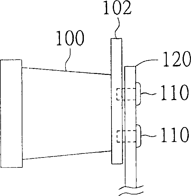
[0022] Please refer to Figure 2A , which shows a side view of the structure of the motor fixed to the mechanism fixing member configured with the motor damping device according to the first embodiment of the present invention. A general motor 200, such as a projector color wheel motor, has a clamping part 202 for locking on the mechanism fixing part 210, and the mechanism fixing part 210 has the above-mentioned three equidistant two-dimensionally arranged locking holes 212 (for To avoid complicated illustrations, the side view only shows two locking holes 212 ), which are used to lock the clamping part 202 and the mechanism fixing part 210 with screws 214 . The motor damping device 220 is disposed on the mechanism fixing part 210 to reduce the vibration of the motor transmitted from the clamping part 202 directly or via the screw 214 to the mechanism fixing part 210 .

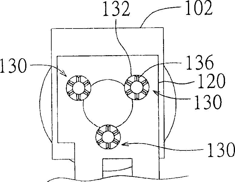
[0023] Please also refer to Figure 2B as well as Figure 2C , respectively plotted Figure 2A Top view...

example 2

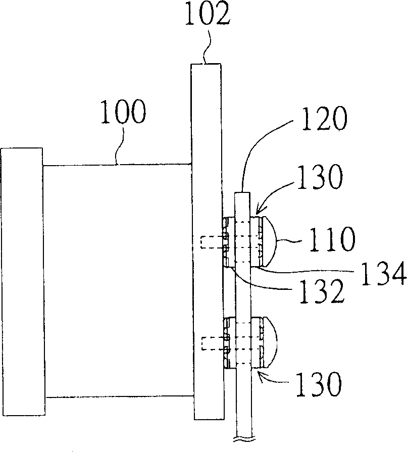
[0027] Please refer to Figure 3A , which shows a side view of the motor fixing structure with the motor damping device according to the second embodiment of the present invention. A general motor 300, such as a projector color wheel motor, has a clamping part 302 for locking on the mechanism fixing part 310, and the mechanism fixing part 310 has the above-mentioned three equidistant two-dimensionally arranged locking holes 312 (for To avoid complicated illustrations, the side view only shows two locking holes 312 ), which are used to lock the clamping part 302 and the mechanism fixing part 310 with screws 314 . The motor damping device 320 is used to reduce the vibration of the motor transmitted to the mechanism fixing part 310 through the clamping part 302 and the screw 314 .

[0028] Please also refer to Figure 3B as well as Figure 3C , respectively plotted Figure 3A A top view and a side view of the middle motor damping device 320 in a deployed state. The motor sho...


PUM


Abstract

A motor damping device includes multiple damping pieces and a connection part, in which, the damping pieces are matched on the fastening holes of the fixing unit to slow down the motor vibration transferred to the fixing unit and the connection part connecting the damping unit.

Description

technical field [0001] The invention relates to a motor damping device, in particular to a motor damping device which blocks high-frequency noise generated by motor rotation. Background technique [0002] Figure 1A It is a structural side view of the existing motor fixed to the mechanism fixture. Please refer to Figure 1A Generally, the motor 100 has a clamping part 102 and is locked on the mechanism fixing part 120 by screws 110 . Since both the clamping part 102 and the mechanism fixing part 120 are sheet metal parts, if no medium is added between them for buffering, the vibration energy of the motor is easily transmitted from the clamping part 102 to the mechanism fixing part 120, making the difference between the two kinds of sheet metal parts between resonant frequencies. Coupled with the multiplication effect of the resonant frequency of different sheet metal materials, it will lead to high-frequency noise. [0003] Figure 1B as well as Figure 1C It is the rea...

Claims


Application Information

Patent Timeline
Patent Type & Authority Applications(China)
IPC IPC(8): H02K5/24
Inventor 黄旭新邱一平沈俊明
Owner BENQ CORP
Features
  • R&D
  • Intellectual Property
  • Life Sciences
  • Materials
  • Tech Scout
  • Unparalleled Data Quality
  • Higher Quality Content
  • 60% Fewer Hallucinations
Learn More