Winder and winding method of filament body

A winding device and thread technology, applied in the direction of transportation and packaging, conveying filamentous materials, thin material processing, etc., to achieve the effect of avoiding the deterioration of characteristics

Active Publication Date: 2006-04-12
SUMITOMO ELECTRIC IND LTD
View PDF1 Cites 16 Cited by
  • Summary
  • Abstract
  • Description
  • Claims
  • Application Information

AI Technical Summary

Problems solved by technology

For this reason, the wound optical fiber has to be discarded, resulting in waste

Method used


Image

  • Winder and winding method of filament body
  • Winder and winding method of filament body
  • Winder and winding method of filament body

Examples


Embodiment Construction

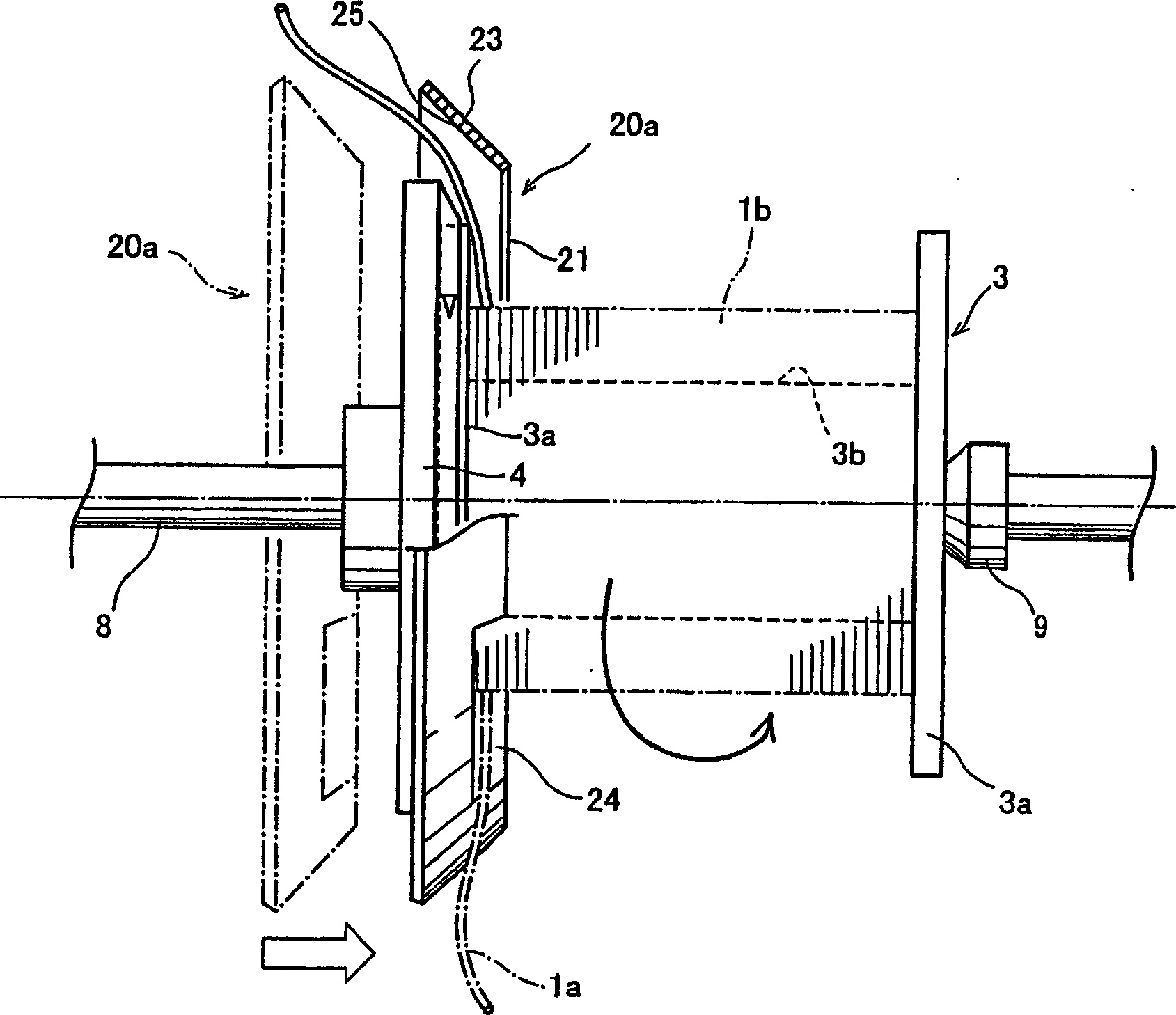
[0027] use image 3 , Figure 4 and Figure 5A ~ Figure 5C Embodiments of the present invention are schematically described. image 3 It is a figure explaining the example of guiding the cut terminal part of the strip to the outside of the winding bobbin, Figure 4 It is an explanatory diagram of an example of the cutting terminal part where the strip is fixed to the fixing part of the ring guide, Figure 5A is a figure showing another example, Figure 5B and Figure 5C It is a diagram illustrating another example of the fixing portion of the annular guide; in the figure, 20a, 20b, 20c, 20d are annular guides, 21 is an opening, 22 is a side wall, 23 is an outer peripheral wall, 24 is a notch, and 25 is a The inner peripheral surface 26 is a fixing part. Other numbers are the same as in Figure 1 and figure 2 is the same as that used in , so its description is omitted.

[0028] Winding device of the present invention, such as image 3 shown, with figure 2 As described ...


PUM


Abstract

A winding device of a wire body having a simple arrangement and a winding method wherein the cut end wire at the end of winding is contained in an annular guide arranged movably on one end part side and does not project from the annular guide. The annular guide (20b) is arranged such that it can cover one flange part of the wire body winding bobbin (3) and provided with a cut (24) for guiding the wire body, wherein the diameter of the inner circumferential surface (25) is enlarged sequentially toward the direction away from the bobbin. The annular guide (20b) may be shaped to have a stop part (26) for preventing the wire body from projecting to the outside of the bobbin. The annular guide (20b) is arranged on the flange part (3a) movably in the axial direction of the bobbin or the annular guide (20b) is constituted of a plurality of parts which are moved to be arranged annularly on the flange part (3a).

Description

technical field [0001] The invention relates to the winding of wires, optical fibers and other wires, especially the winding device and winding method for cutting off the terminal part of the wires when winding the wires at high speed. Background technique [0002] Now, when continuously sending wires, optical fibers and other wires are wound on the winding bobbin at high speed, the progress of the wires must not be interrupted from the completion of the specified amount of winding full winding bobbin to the empty winding bobbin starting a new winding. Gives a toggle for wrapping. Fig. 1 is a diagram illustrating the processing of the cut end thread at the end of the existing winding. In the figure, 1 is a thread object, 1a is a cut end thread, 1b is a winding body, 2 is a winding roller, and 3, 3' are winding wires Tube, 3a is the flange part, 3b is the tube body part, 4 is the claw wheel, 5 is the thread moving arm, 6 is the fixed claw, and 7 is the cutter. [0003] In F...

Claims


Application Information

Patent Timeline
Patent Type & Authority Applications(China)
IPC IPC(8): B65H67/04B65H54/72B65H67/052
CPCB65H2701/32B65H67/052B65H54/72B65H67/04
Inventor 山崎卓桑原一也
Owner SUMITOMO ELECTRIC IND LTD
Why Eureka
Try Eureka