

Rotating electrical machine
A mechanical and electric technology, applied in the direction of electronic commutation motor control, mechanical equipment, electrical components, etc., can solve the problem of high manufacturing cost
- Summary
- Abstract
- Description
- Claims
- Application Information
AI Technical Summary
Problems solved by technology
Method used
Image

Examples
Embodiment Construction
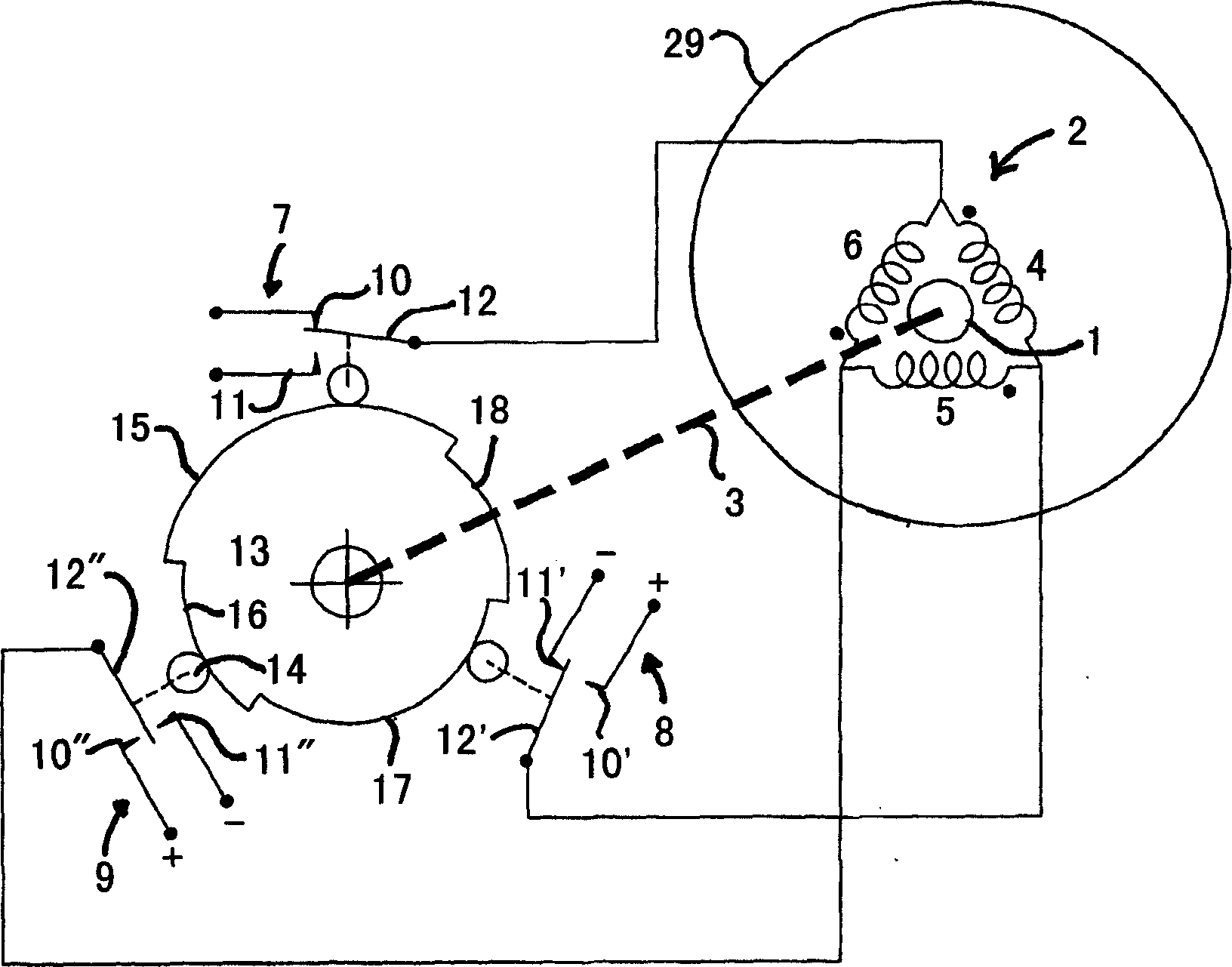
[0026] figure 1 A two-pole rotating electromechanical machine according to the invention is shown. The machine comprises a housing 29 surrounding the rotor 1 and the field winding 2 . The rotor 1 is mounted on a shaft 3 for rotation within a housing and includes permanent magnets for establishing the rotor magnetic field. The field winding 2 is arranged around the rotor 1 and comprises three delta-connected windings 4 , 5 , 6 . The construction of this rotor 1 and field winding 2 is known in the prior art and does not require further elaboration.
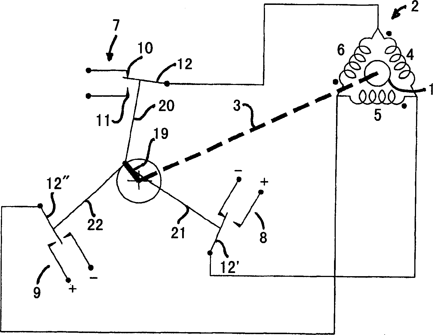
[0027] In the described machine configuration, current is supplied to the field windings 4, 5, 6 through three single pole changeover switches 7, 8, 9 operated in sequence. The first fixed contact 10 of each changeover switch 7, 8, 9 is connected to the positive (+) side and the second fixed contact 11 is connected to the negative (-) side of the DC power supply (not shown). A moving switch contact 12 is connected to the field w...
PUM
 Abstract
Description
Claims
Application Information