
Transmitter head and a system for contactless energy transmission

一种能量传输、传送器的技术,应用在变压器、电感器、固定电感器等方向,能够解决效率低等问题,达到高效率、降低数量、实现效率的效果

Inactive Publication Date: 2006-04-19
SEW-EURODRIVE GMBH & CO KG
View PDF6 Cites 15 Cited by
  • Summary
  • Abstract
  • Description
  • Claims
  • Application Information

AI Technical Summary

Problems solved by technology

[0005] A flat arrangement is known from DE 19746919 A1, but this arrangement leads to lower efficiency in energy transmission

Method used


Image

  • Transmitter head and a system for contactless energy transmission
  • Transmitter head and a system for contactless energy transmission
  • Transmitter head and a system for contactless energy transmission

Examples


Embodiment Construction

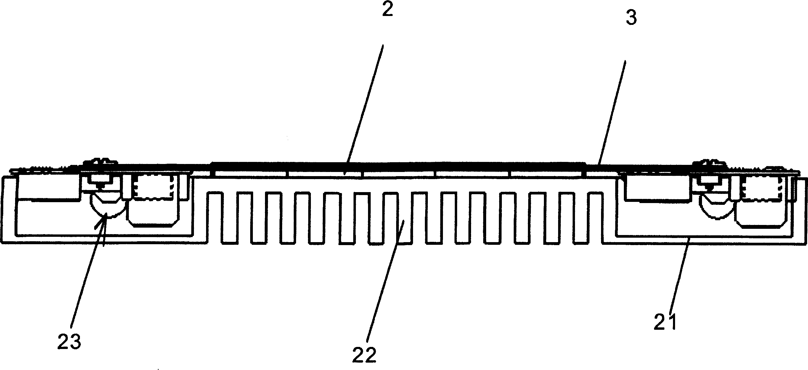
[0040] Figure 1a A transmitter head according to the invention shown in , where in Figure 1b An enlarged detail of the left end region is shown in . The conveyor head is designed to be flat and requires little installation space.

[0041] Here, a ferrite core 2 is mounted and connected to the carrier 1 , in particular as an adhesive connection or as a detachable connection, such as a screw connection or the like.

[0042] Arranged on the ferrite core 2 is a multilayer circuit board with layers ( 3 , 4 , 5 ) with copper conductor tracks designed as flat windings and thus formed on the circuit board.

[0043] Here, in another exemplary embodiment according to the invention, a single flat spiral winding is arranged as a conductor track of a single-layer printed circuit board, but in this case only low electrical power can be transmitted.

[0044] In another embodiment according to the present invention, especially according to Figure 1a with 1b In an embodiment of the prese...


PUM


Abstract

The invention relates to a transmitter head for a system for contactless energy transmission. The inventive transmitter head comprises a support connected to at least one ferrite core. According to said invention, the ferrite core is embodied at least partially in the E-form and a flat winding is arranged around one leg of the E.

Description

technical field [0001] The invention relates to a transmitter head and a system for contactless energy transmission. Background technique [0002] A device for contactless energy transmission is known from DE 10053373 A1. Therein, a transmitter head is described which is capable of inductive energy transmission and has a certain number of turns. [0003] Systems for contactless energy transmission are known from DE 4446779 C2 and DE 19735624 C1, in which the transmission path consists of a stationary central conductor and an aluminum profile as return line. The central conductor is here surrounded by a U-shaped core along which the conveyor head is movable. A winding is provided on the U-shaped core. Overall, the conveyor head requires a relatively large construction volume. [0004] A system for contactless energy transmission is likewise known from WO 92 / 17929. The transmission section includes inflow and return conductors in the form of linear conductors. A transmit...

Claims


Application Information

Patent Timeline
Patent Type & Authority Applications(China)
IPC IPC(8): H02J5/00H01F17/00H01F19/08H01F38/14
CPCH01F17/0013H01F19/08H01F2038/143H01F38/14
Inventor J·施密特G·贝克尔L·波德别尔斯基M·努尔格
Owner SEW-EURODRIVE GMBH & CO KG
Learn More