Imaging lens system

A technology of camera lens and camera surface, applied in the field of camera lens, can solve the problems of difficulty in achieving small size and light weight, increased manufacturing cost, and large number of parts, and achieves the effect of achieving small size and light weight, good manufacturing performance and effective volume

Inactive Publication Date: 2006-04-26
ENPLAS CORP
View PDF2 Cites 3 Cited by
  • Summary
  • Abstract
  • Description
  • Claims
  • Application Information

AI Technical Summary

Problems solved by technology

[0006] At this time, in the three-lens system, since various aberrations related to optical performance degradation can be effectively corrected, although extremely high optical performance can be obtained, the problem with the three-lens system is that due to the large number of parts, Therefore, it is difficult to achieve small size and light weight, and the high precision required for each component part also increases the manufacturing cost.
[0011] However, in recent years, for this type of imaging lens, in addition to the requirement of small size and light weight, there is an increasing demand for further improvement in optical performance. However, there is a problem that it is difficult to achieve a balance between small size and light weight and further improvement of optical performance, and it is also difficult to match the characteristics of the sensor (incident angle to the sensor)

Method used


Image

  • Imaging lens system
  • Imaging lens system
  • Imaging lens system

Examples


Embodiment

[0150] Below, refer to Figure 2-Figure 9 Embodiments of the present invention will be described.

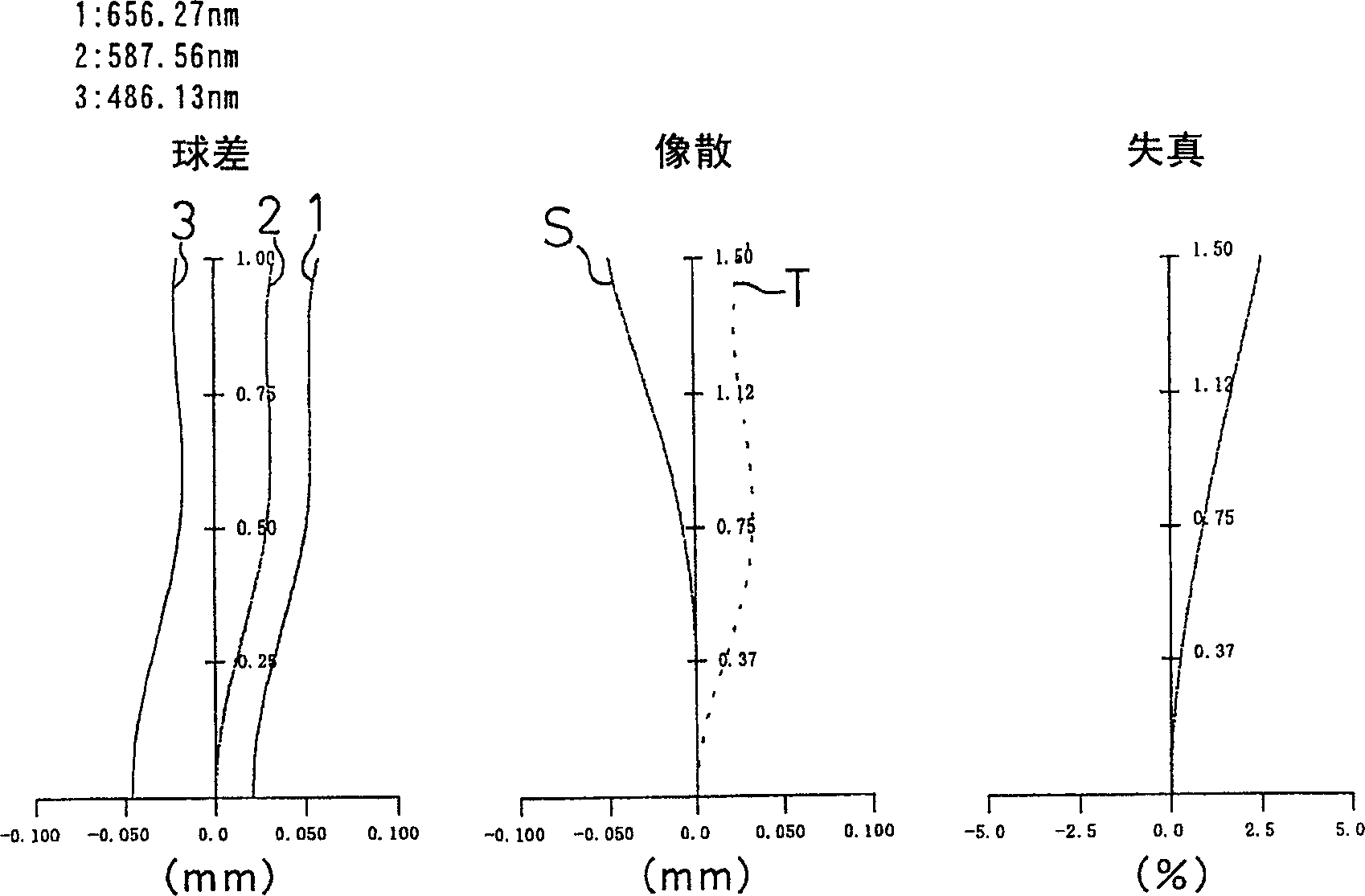
[0151] Here, in this embodiment, Fno represents the F component, and r represents the radius of curvature of the optical surface (in the case of a lens, the radius of curvature of the center). And d represents the distance to the next optical plane. Also, nd represents the refractive index of each optical system when irradiated with d-line (yellow), and vd represents the Abbe number of each optical system when the same d-line is applied.

[0152] k, A, B, C, and D represent coefficients in the following formula (12). That is, when the direction of the optical axis 8 is the Z axis, the direction perpendicular to the optical axis 8 is the X axis, the propagation direction of light is positive, k is the cone coefficient, A, B, C, D are the aspheric coefficients, and r is The aspherical shape of the lens is expressed by the following formula when the curvature radius is used.

...

no. 1 example

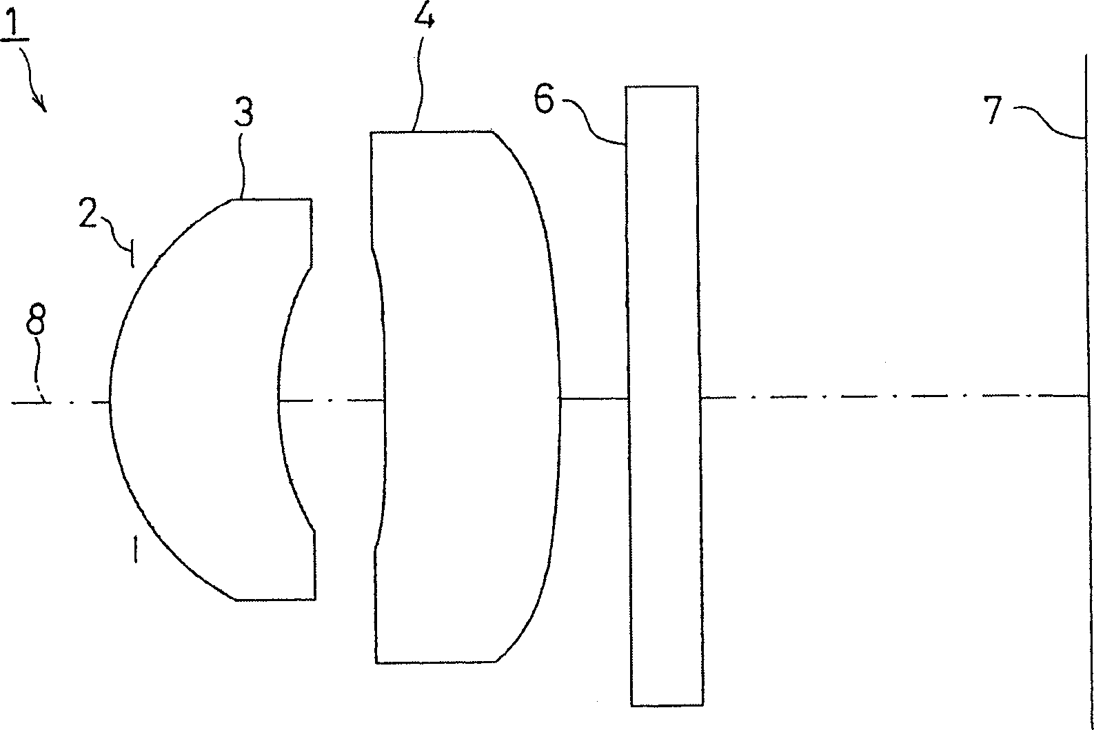
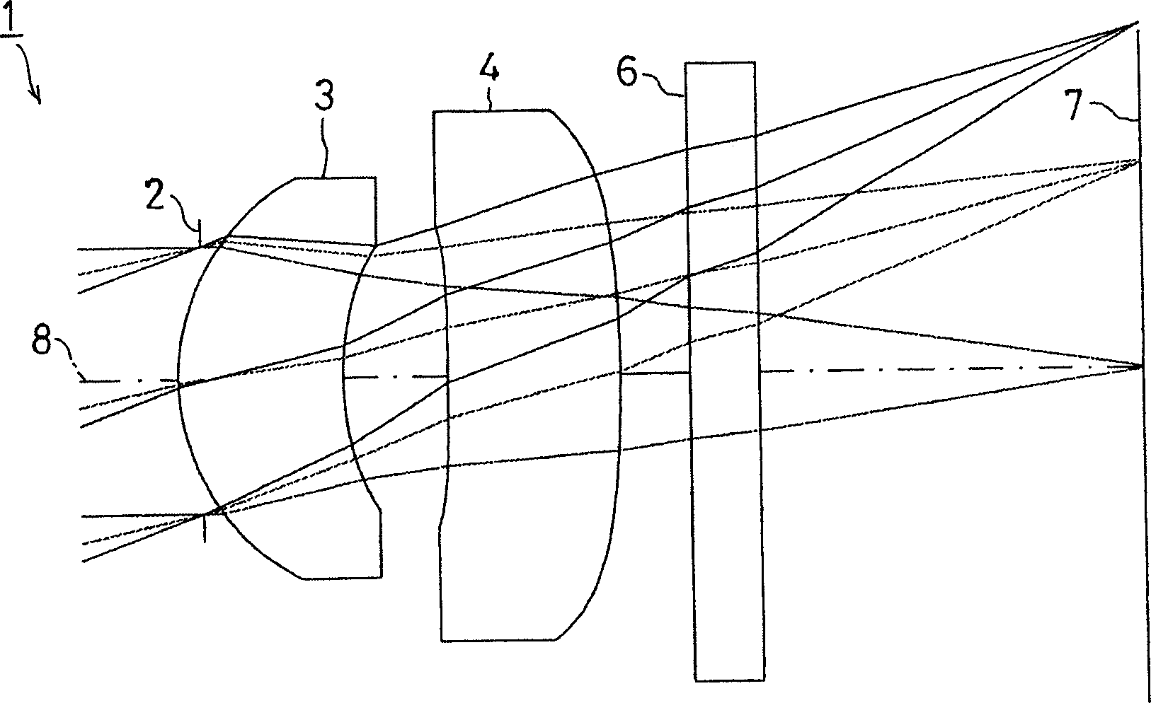
[0155] figure 2 Represents the first embodiment of the present invention, in this embodiment, with figure 1 The imaging lens 1 of the shown structure is also configured with a diaphragm 2 on the object side of the first surface of the first lens 3, and a cover as an optical filter 6 is arranged between the second surface of the second lens 4 and the imaging surface 7. Glass. In addition, the first surface of the first lens 3 is located closer to the object side than the aperture 2 through the aperture 2 .

[0156] The imaging lens 1 of the first embodiment is set under the following conditions.

[0157] lens data

[0158] face number

r

d

nd

vd

(object point)

1 (first lens first side)

2 (the second side of the first lens)

3 (first side of the second lens)

4 (Second lens second side)

5 (covering the first side of the glass)

6 (covering the second side of the glass)

1.033

1.387

-39.796

-6.02...

no. 2 example

[0164] Figure 4 represents a second embodiment of the present invention, in this embodiment, with figure 1 The imaging lens 1 having the structure shown is similarly provided with a diaphragm 2 disposed on the object side of the first surface of the first lens 3, and an optical filter 6 is disposed between the second surface of the second lens 4 and the imaging surface 7. Cover glass. In addition, the first surface of the first lens 3 is located closer to the object side than the aperture 2 through the aperture 2 .

[0165] The imaging lens 1 of this second embodiment is set under the following conditions.

[0166] lens data

[0167] face number

r

d

nd

vd

(object point)

1 (first lens first side)

2 (the second side of the first lens)

3 (first side of the second lens)

4 (Second lens second side)

5 (covering the first side of the glass)

6 (covering the second side of the glass)

1.115

1.478

217.3...


PUM


Abstract

The present invention provides a compact imaging lens. The compact imaging lens comprises, from the object side to the image side, a diaphragm (2), a first positive meniscus lens (3) with a positive focal crescent shape which the convex surface of which facing the object side, and a second positive lens (4) the convex surface of which facing the image surface side, wherein following inequalities are satisfied 1.25>=L / fl>=0.8, 0.55>=f1 / f2>=0.2, 1.8>=f1 / fl>=1, 4>=f2 / fl>=1.5, 1>=d2 / d1>=0.5, 0.27>=d1 / fl>=0.1, 0.27 >=d3 / fl>=0.1 where, L: entire length of the lens system, Fl: focal distance of entire lens system, f1: focal distance of the first lens, f2: focal distance of the second lens, d1: center thickness of the first lens, d2: distance between the first lens and second lens on the optical axis, d3: center thickness of the second lens.

Description

technical field [0001] The present invention relates to an imaging lens, and more particularly to an imaging device for forming images of objects such as scenery and people on the imaging surface of a solid-state imaging element such as a CCD or CMOS disposed in a notebook computer, a videophone, a mobile phone, etc. An imaging lens consisting of two lenses that achieves compactness and weight reduction, improved optical performance, and improved manufacturability. Background technique [0002] In recent years, demand for video cameras using solid-state imaging elements such as CCDs and CMOSs, which are used in mobile phones, notebook computers, and video phones, for example, has increased significantly. Since such a camera must be arranged in a limited installation space, it is required to be small and lightweight. [0003] Accordingly, the imaging lens used for such a video camera is also required to be compact and lightweight. As such an imaging lens, a single-lens syste...

Claims


Application Information

Patent Timeline
Patent Type & Authority Applications(China)
IPC IPC(8): G02B7/04G02B13/18
Inventor 齐藤共启
Owner ENPLAS CORP
Why Eureka
Try Eureka