

Ignitor assembly
A technology of igniters and components, applied in the direction of weapon accessories, vehicle parts, chemical instruments and methods, etc., to achieve the effect of preventing moisture absorption or deterioration
- Summary
- Abstract
- Description
- Claims
- Application Information
AI Technical Summary
Problems solved by technology
Method used
Image

Examples
Embodiment 1
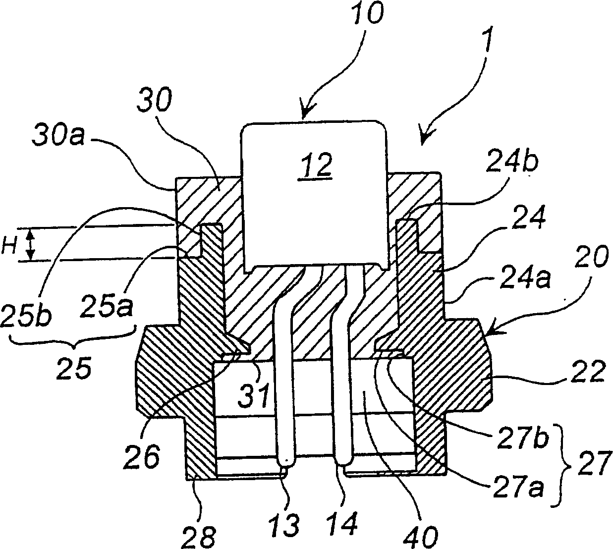
[0062] according to figure 1 , an embodiment of the igniter assembly will be described. figure 1 is an axial (longitudinal) cross-sectional view of the igniter assembly.
[0063] The igniter assembly 1 includes an igniter 10 and a substantially cylindrical metal collar 20 for supporting the igniter 10 from the outside, a resin 30 is filled between the igniter 10 and the metal collar 20, and the igniter 10 and metal collar 20 are combined together.
[0064] The igniter 10 comprises an ignition part 12 provided with an ignition charge and two conductive pins 13, 14 forming a circuit supplying the current required to ignite and burn the ignition charge.
[0065] The ferrule 20 includes: a collar body portion 22 having a maximum outer diameter, a cylindrical protrusion 24 extending axially upward from the collar body portion 22 , an annular protrusion extending radially inward from the collar body portion 22 26 , and a skirt 28 extending axially downward from the collar body po...
Embodiment 2
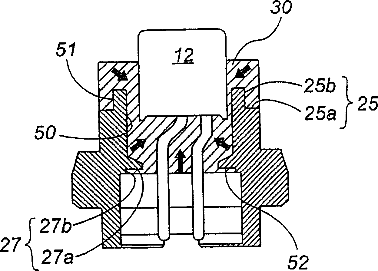
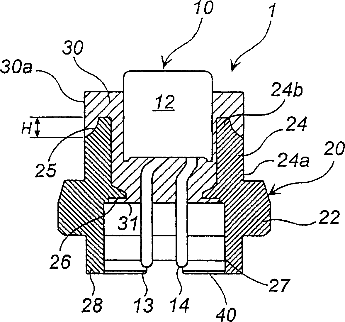
[0083] according to image 3 , another embodiment of the igniter assembly will be described. image 3 is an axial (vertical) sectional view of the igniter assembly. image 3 The igniter assembly shown is 1 with the figure 1 The difference of the illustrated igniter assembly 1 is only that an annular inclined surface 25 is provided instead of the cylindrical step 25, and image 3 The igniter assembly shown is 1 with the figure 1 The igniter assembly in the function in the same way.
[0084] During the curing process, due to the shrinkage of the resin, the figure 2 When a gap is generated at the shown interface 50, the interface between the annular inclined surface 25 and the resin 30 (corresponding to figure 2 The interface of the interface 51) is pressed by the shrinking resin. Thus, even in the case where a gap is generated at the interface 50 due to shrinkage of the resin, the gap is prevented from being formed at the interface 51 . And thus achieve the first effect...
Embodiment 3
[0088] Below, will explain figure 1 and image 3 Other embodiments of igniter assemblies are shown. exist figure 1 and image 3 In the igniter assembly shown in , by providing the metal collar 20 with such strength that it is slightly deformed when subjected to the injection pressure of the resin injection molding method, and by adjusting the injection conditions of the resin, it is possible to achieve the above-mentioned first effect igniter assembly. The following will be based on figure 1 described as follows.
[0089] exist figure 1 , including a cylindrical protrusion 24 (which includes a cylindrical step portion 25) extending axially upward from the collar main body 22 and an annular protrusion 26 (which includes a ring shaped portion) extending radially inward from the collar main body 22. The metal collar 20 of the stepped portion 27 ) is made of aluminum or an aluminum alloy, and is slightly deformed due to an injection pressure of not less than 9 MPa applied a...
PUM
 Abstract
Description
Claims
Application Information