
Eureka
For R&D, Eureka makes reading and utilizing patents & technical documents easy.
Eureka AIR
Designed for self-driven R&D workflows. Generate viable solutions, solve complex R&D challenges, empower your innovation with AI.

Eureka Materials
Designed for material experts only. Revolutionize your material R&D, from search, analyze, to developing new materials.

TechResearch
Generate reliable direction feasibility study reports for your R&D in just a few steps.

TechSeek
Discover and master advanced knowledge NOW. Basics, ideas, possibilities, all at once.

TechMind
As an expert in R&D Theories, TechMind can generates customized viable solutions instantly.

TechRisk
Analyze your overall solution with one click, know your potential R&D risks in advance.

TechMonitor
Get weekly tech updates, stay abreast of the latest tech innovations and key insights.
Novel steel-concrete combined beam
A technology for reinforced concrete slabs and composite beams, which is applied in the field of bridges and building support components and composite beams. It can solve the problems of manpower consumption, working hours, inability to fully guarantee, and affect the safety and reliability of composite beams, and achieve large bonding force and shear resistance. Strong cutting ability and material saving effect
- Summary
- Abstract
- Description
- Claims
- Application Information
AI Technical Summary
Problems solved by technology
Method used
Image

Examples
Embodiment 1
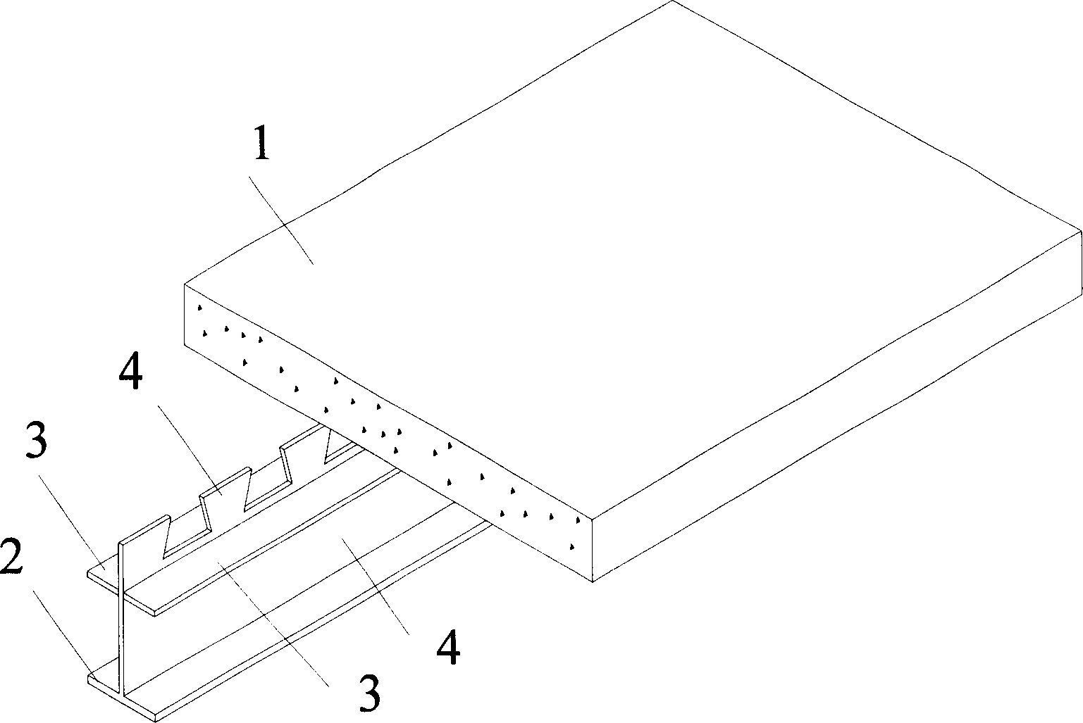
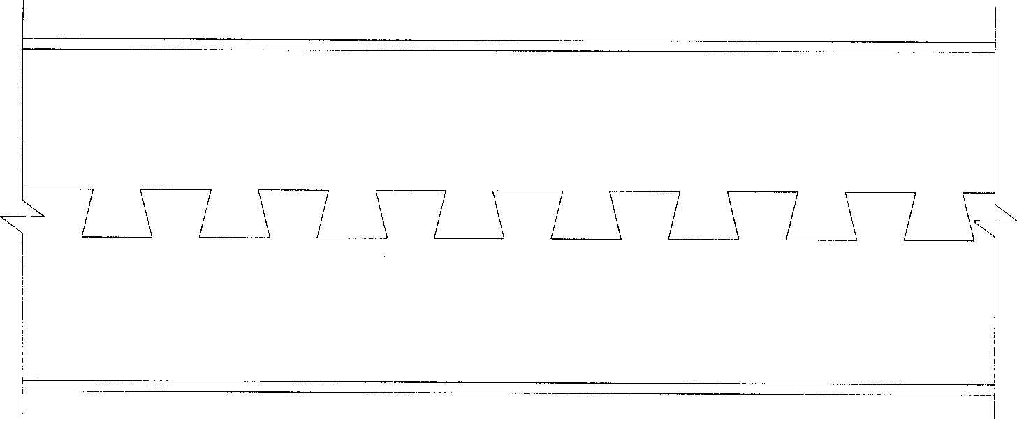
[0017] like figure 1 , image 3 As shown, an H-shaped steel-concrete composite beam of the present invention comprises a reinforced concrete slab 1, a lower flange of the steel beam 2, two upper flanges of the steel beam 3 and a steel beam web 4, and one side of the steel beam web 4 is sawtooth The shape of the sawtooth is an inverted isosceles trapezoid. The sawtooth protrudes from the upper flange of the steel beam. The sawtooth edge of the web is cut from the H-shaped steel web along the broken line. The entire sawtooth extends into the upper reinforced concrete slab to form the shear connection of the composite beam. The upper flange 3 of the 2 steel beams is composed of two steel plates, and the height is located at the root of the sawtooth. The lower flange 2 of the steel beam and the web 4 of the steel beam are the lower flange and web of H-beam, and the 2 upper flanges and the web are welded by welding connect.
Embodiment 2
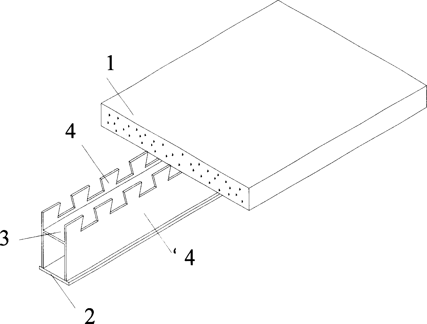
[0019] like figure 2 , Figure 4 As shown, a box-shaped steel-concrete composite beam of the present invention includes a reinforced concrete slab 1, a lower flange 2 of a steel beam, an upper flange 3 of a steel beam and two steel beam webs 4, and one side of the steel beam web 4 is a belt The sawtooth edge, the shape of the sawtooth is an inverted isosceles trapezoid, the sawtooth protrudes from the upper flange of the steel beam, the sawtooth edge of the web is cut from the steel plate along the broken line, the upper flange 3 of the steel beam is located between the two sawtooth edge webs, and the height is located at the root of the sawtooth, and the upper Flange and 2 webs are connected by welding.
PUM
 Abstract
Description
Claims
Application Information
 - R&D Engineer
- R&D Manager
- IP Professional
- Industry Leading Data Capabilities
- Powerful AI technology
- Patent DNA Extraction
Browse by: Latest US Patents, China's latest patents, Technical Efficacy Thesaurus, Application Domain, Technology Topic, Popular Technical Reports.
© 2024 PatSnap. All rights reserved.Legal|Privacy policy|Modern Slavery Act Transparency Statement|Sitemap|About US| Contact US: help@patsnap.com