Liquid crystal display panel and bar code reading system using same
A liquid crystal display and bar code technology, which is applied to record carriers, optics, instruments and other directions used by machines, can solve problems such as inability to read, and achieve the effect of correct reading.
- Summary
- Abstract
- Description
- Claims
- Application Information
AI Technical Summary
Problems solved by technology
Method used
Image

Examples
no. 1 Embodiment approach
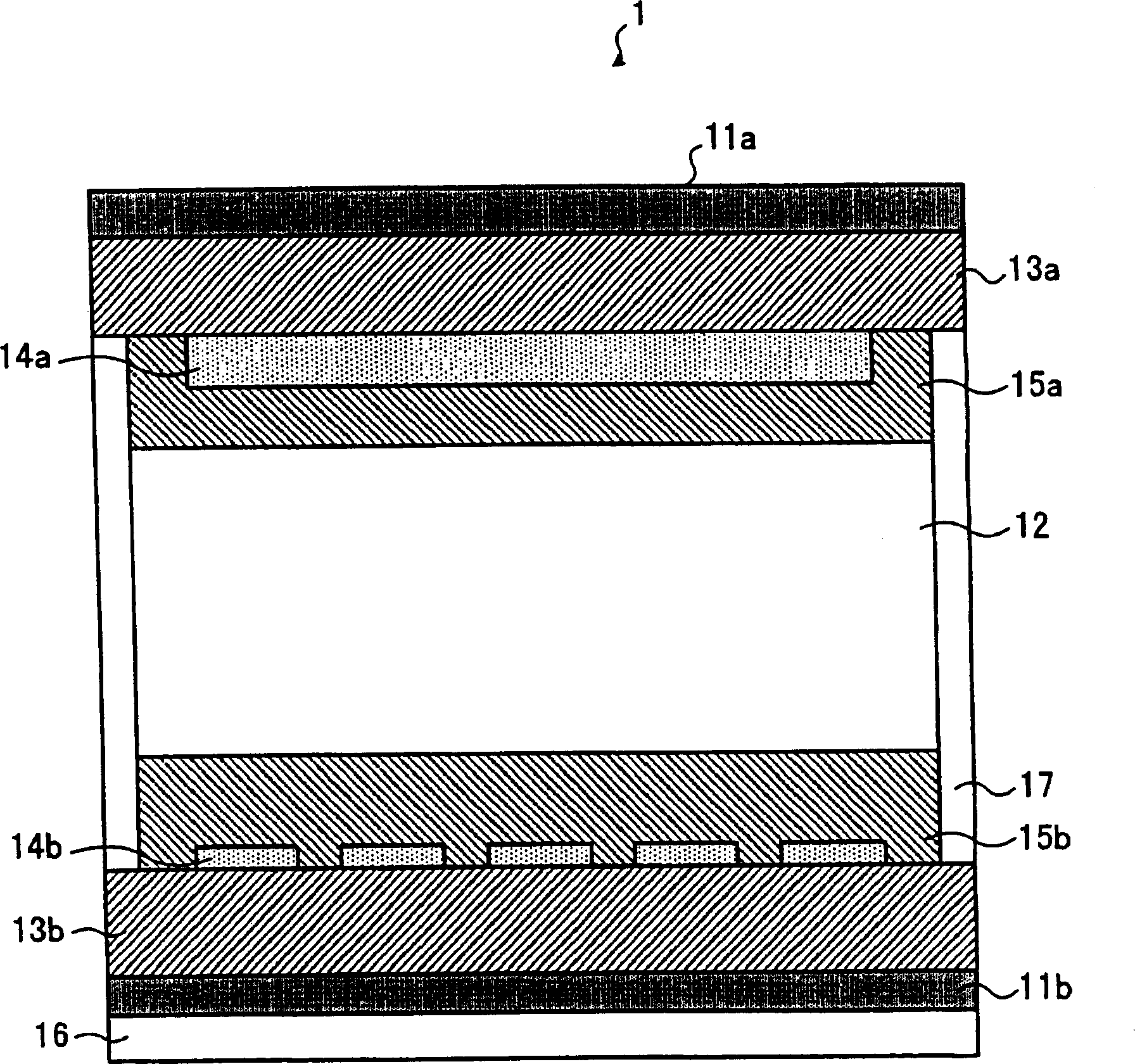
[0049] figure 2 It is a sectional view showing the structure of the liquid crystal display panel according to the embodiment of the present invention. Such as figure 2 As shown, the liquid crystal display panel 1 is composed of a pair of glass substrates 13a, 13b sandwiching a liquid crystal layer 12 having a thickness of about 2 μm, and a sealing material 17 connecting the two glass substrates 13a, 13b. On the opposing surfaces of the glass substrates 13a, 13b, a plurality of pixel dots are arranged in a matrix to form electrodes (ITO) 14a, 14b, and alignment films 15a, 15b are arranged thereon for alignment treatment.
[0050] Furthermore, a first polarizing plate 11a is provided on the outside of one glass substrate (hereinafter referred to as "first glass substrate") 13a. On the outside of another glass substrate (hereinafter referred to as "second glass substrate") 13b, a second polarizing plate 11b having a polarization axis different from that of the first polarizin...
no. 2 Embodiment approach
[0066] The relationship between the transmission axis direction of the first polarizing plate 11a, the molecular major axis direction of the ferroelectric liquid crystal, and the orientation of the barcode in the second embodiment is different from that in the first embodiment. The other structures are the same as those of the first embodiment, so they will not be described again.
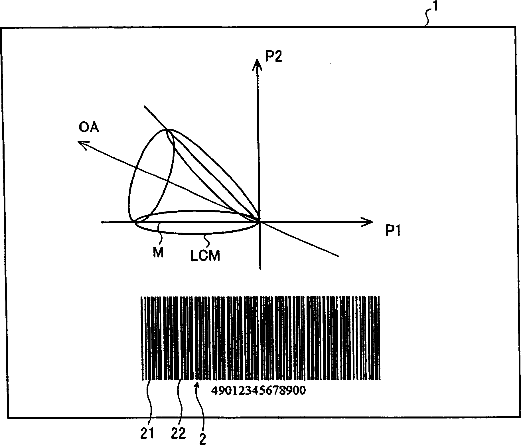
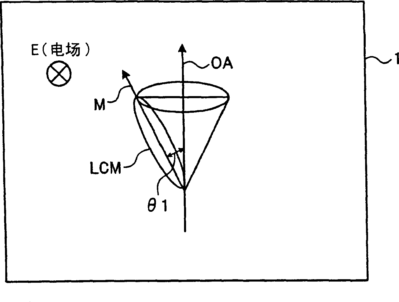
[0067] Figure 8 or Figure 9 It is a graph showing the relationship between the transmission axis direction of the first polarizing plate 11a, the molecular major axis direction of the ferroelectric liquid crystal, and the orientation of the barcode in the second embodiment. Such as Figure 8 or Figure 9 As shown, in the second embodiment, the angle formed by the average molecular major axis direction M of the liquid crystal in the first ferroelectric state and the transmission axis P1 of the first polarizing plate 11a is 45° or approximately 45°. Since the angle formed by the transmission ax...
no. 3 Embodiment approach
[0073] Figure 10 It is a block diagram showing the configuration including the drive circuit unit of the liquid crystal display panel 1 according to the third embodiment. Such as Figure 10 As shown, the liquid crystal display screen 1 has: a display part 31 for displaying a display 3 of a barcode 2 and letters or numbers, and a display 4 of numbers under the barcode 2, and a scanning side IC (integrated circuit) for sequentially selecting the scanning electrodes of the display part 31 ) 32, a signal side IC 33 that applies a voltage corresponding to the display data to the signal electrodes of the display unit 31, and a display control unit 34 that controls the ICs 32 and 33 on the scanning side and the signal side.
[0074] In addition, the liquid crystal display 1 further includes a data conversion unit 35 and a sensor 36 . The data conversion unit 35 converts the original display data into data in which the orientation displayed by the original display data is rotated b...
PUM
 Abstract
Description
Claims
Application Information
 - R&D Engineer
- R&D Manager
- IP Professional
- Industry Leading Data Capabilities
- Powerful AI technology
- Patent DNA Extraction
Browse by: Latest US Patents, China's latest patents, Technical Efficacy Thesaurus, Application Domain, Technology Topic.
© 2024 PatSnap. All rights reserved.Legal|Privacy policy|Modern Slavery Act Transparency Statement|Sitemap