Nozzle having a nozzle body with heated and unheated nozzle body segments

A technology of body parts and nozzles, applied in the field of injection molding devices

Active Publication Date: 2006-05-10
标准模具(2007)有限公司
View PDF5 Cites 6 Cited by
  • Summary
  • Abstract
  • Description
  • Claims
  • Application Information

AI Technical Summary

Problems solved by technology

The disadvantage of this arrangement is that there is usually a temperature peak in the middle of the nozzle, as these conventional heaters also apply heat along the entire length of the nozzle and the heat loss in the middle is negligible compared to the heat loss at the end of the nozzle

Method used


Image

  • Nozzle having a nozzle body with heated and unheated nozzle body segments
  • Nozzle having a nozzle body with heated and unheated nozzle body segments
  • Nozzle having a nozzle body with heated and unheated nozzle body segments

Examples


Embodiment Construction

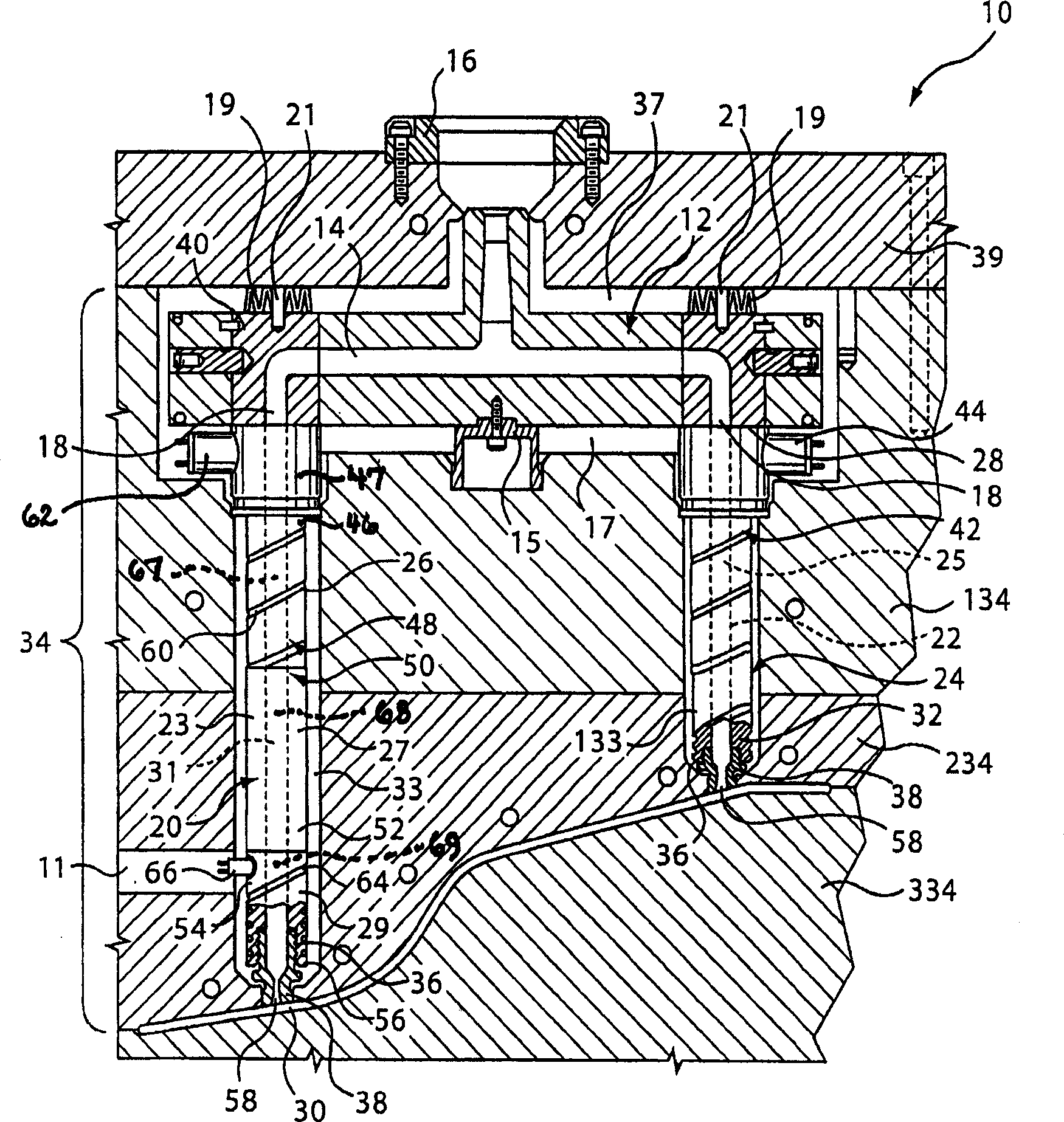
[0031] now refer to figure 1 , generally shown as an injection molding apparatus 10 . Injection molding apparatus 10 includes a manifold 12 having a manifold channel 14 extending therethrough. A manifold sleeve 16 is located at the inlet of the manifold channel 14 to receive a melt flow of moldable material from a machine nozzle (not shown) and to route the melt flow to a manifold outlet 18 . A heating element (not shown) heats the manifold 12 to maintain the melt flow through the melt channel 14 at the desired temperature. The manifold's heating elements may be embedded in or otherwise surround the surface of the manifold 12 . The manifold 12 is held in place by a central retaining ring 15 which spans the insulating space 17 between the hot manifold 12 and the cold plate 134 . Another insulating space 37 with a predetermined width is located between the heat manifold 12 and the cold packing template 39 . The pressure plate 19 is mounted by means of screws 21 to create an ...


PUM


Abstract

A nozzle for an injection molding apparatus includes a nozzle body having a first nozzle body portion, a second nozzle body portion, and a third nozzle body portion, the second nozzle body portion movably connected to at least one of the first nozzle body portion and the third nozzle body portion, the first nozzle body portion and the third nozzle body portion being heated by the first and second nozzle heaters, respectively, or by a heater jacket tube heating, the heater sleeve has a cutout along the length of a second nozzle body portion that is substantially free of nozzle heaters to allow the second nozzle body portion to pass through with the first nozzle body The portion is passively heated in contact with the third nozzle body portion.

Description

technical field [0001] The present invention generally relates to an injection molding apparatus, particularly a nozzle having a nozzle body comprising a plurality of nozzle body parts, and more particularly, the present invention relates to a nozzle for an injection molding machine, wherein the nozzle body At least one nozzle body portion is heaterless. Background technique [0002] As is well known in the art, hot runner injection molding systems include manifolds for delivering pressurized melt from an inlet to one or more manifold outlets. Typically most nozzles are connected to manifold outlets for delivering melt to multiple cavities. [0003] Some applications, such as molding large automotive parts, require the use of nozzles of different lengths, where each nozzle communicates with a single manifold. For example, when injecting molten material into a mold cavity with an uneven surface facing the nozzles, then one of the nozzles must be longer than the other nozzle...

Claims


Application Information

Patent Timeline
Patent Type & Authority Applications(China)
IPC IPC(8): B29C45/20B29C45/03B29C45/22B29C45/27B29C45/28B29C45/38B29C45/74
CPCB29C45/27B29C45/2701B29C45/2737B29C45/2738B29C45/2806B29C2045/2717B29C2045/2741B29C2045/2754B29C2045/2766B29C2045/2774B29C2045/2777
Inventor J·费希尔F·费里G·科洛尼科P·塔巴斯
Owner 标准模具(2007)有限公司
Why Eureka
Try Eureka