

Duplexer
一种双工器、接收滤波器的技术,应用在使用表面声波的双工器领域,能够解决不适于SAW滤波器的相位匹配电路等问题,达到低带内插入损耗、尺寸小、高绝缘特性的效果
- Summary
- Abstract
- Description
- Claims
- Application Information
AI Technical Summary
Problems solved by technology
Method used
Image

Examples
no. 1 example
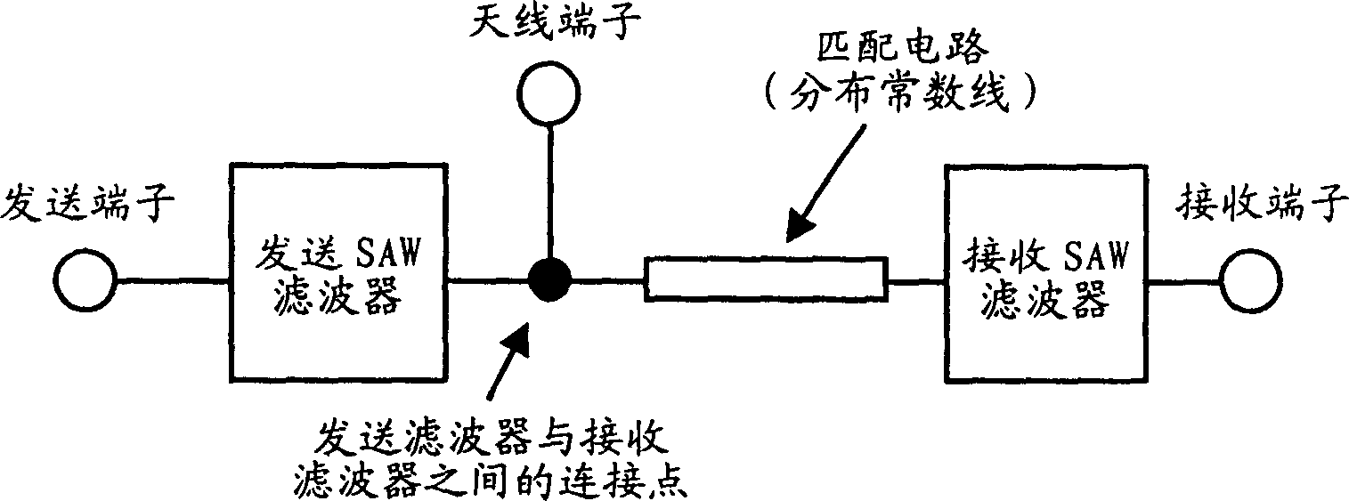
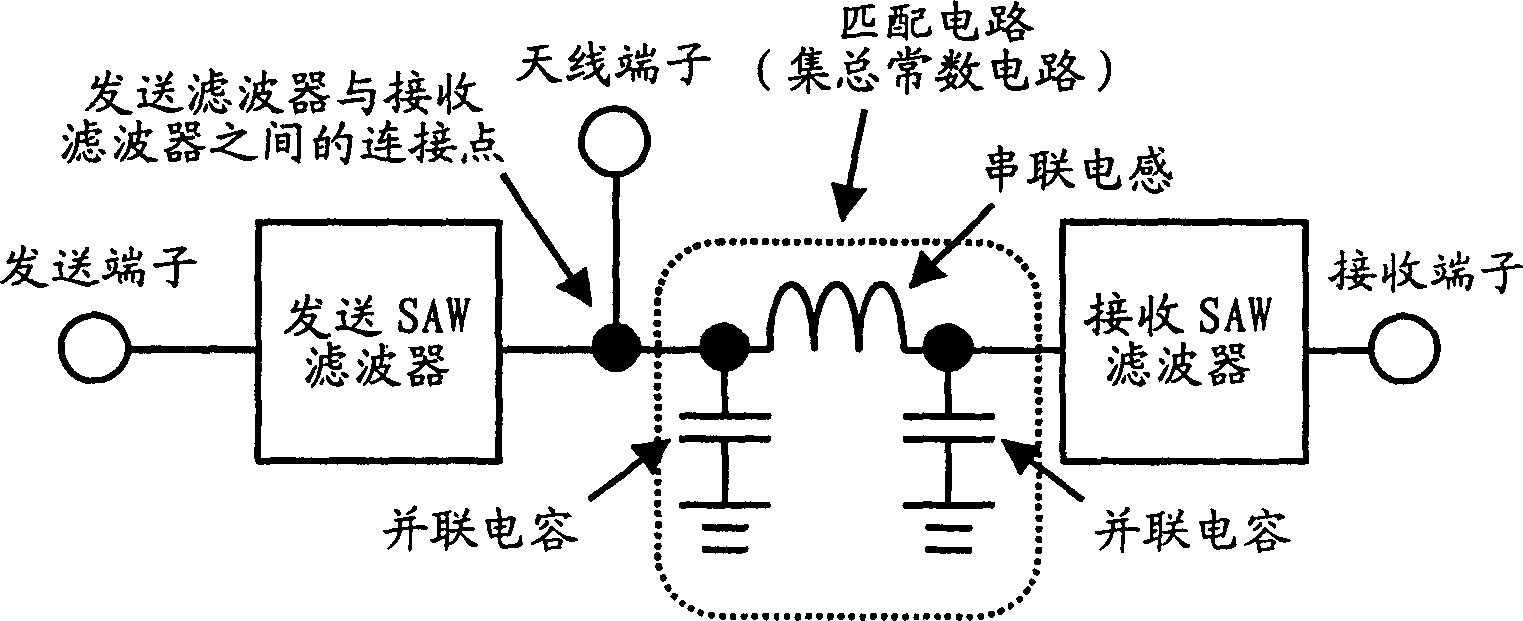
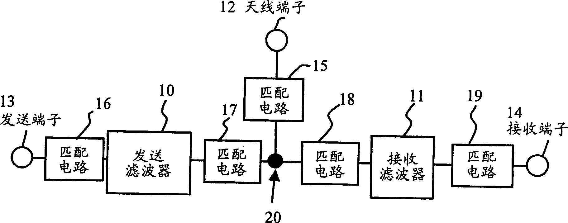
[0037] image 3 is a block diagram of the structure of the duplexer according to the first embodiment of the present invention. The duplexer includes a transmission filter 10 , a reception filter 11 , an antenna terminal (common terminal) 12 , a transmission terminal 13 and a reception terminal 14 . Both the transmit filter 10 and the receive filter 11 are surface acoustic wave (SAW) filters. Hereinafter, the transmission filter 10 and the reception filter 11 may also be referred to as the transmission SAW filter 10 and the reception SAW filter 11 . The duplexer also includes phase matching circuits 15 to 19 . However, the duplexer of the present invention does not necessarily have to include the phase matching circuits 15 to 19 . Rather, the phase matching circuits 15 to 19 can be selectively used to obtain the desired characteristics. For example, only the matching circuit 18 may be employed. The matching circuit in this duplexer is a reactive circuit formed by lumped c...
no. 2 example
[0047] Figure 11A A duplexer of the second embodiment is shown, which includes a matching circuit 18 on the input side of the receive filter 11 and a matching circuit 19 on the output side of the receive filter 11 . like Figure 11B As shown, the two matching circuits 18 and 19 are formed on a quartz substrate 21, which is an insulating substrate. have Figure 11B The filter chip 44 of the shown quartz substrate 21 includes not only Figure 5A The shown components further include an inductance L3 forming the matching circuit 19, and receiving terminal connection pads 45 and reception filter connection pads 46 connected to both ends of the inductance L3. Similar to the inductors 22 and 23 , the inductor L3 is of a spiral type, and is formed directly on the surface of the quartz substrate 21 . Thus, not only is the capacitance coupled between the inductances L1 and L2 forming the matching circuit 18 reduced, but also the capacitance coupled between the inductance L3 of the ...
no. 3 example
[0050] Figure 13 It is a plan view of a duplexer according to a third embodiment of the present invention. The duplexer has a structure in which the transmission filter 10 and the reception filter 11 formed of the SAW filter, the parallel inductances 62 and 63 and the series capacitance 64 are formed on a single piezoelectric substrate 51 . Parallel inductors 62 and 63 and series capacitor 64 form a Figure 4B The matching circuit 18 of the circuit structure shown (see image 3 ). Parallel inductors 62 and 63 are helical coils, and series capacitor 64 has eg Figure 5B shown structure. An antenna terminal connection pad 52 , a transmission terminal connection pad 53 , a reception terminal connection pad 54 , and ground pads 55 and 56 are also formed on the piezoelectric substrate 51 . Since the transmission filter 10, the reception filter 11, and the matching circuit 18 are formed on a single piezoelectric substrate 51, the number of required parts is reduced, and thus t...
PUM
 Abstract
Description
Claims
Application Information