Welding fixture and welding method for vacuum tube

A welding fixture and vacuum tube technology, applied in welding equipment, auxiliary welding equipment, welding/cutting auxiliary equipment, etc., can solve the problems of vacuum tube scrapping, affecting production efficiency, wasting manpower and material resources, etc., to ensure performance, simple structure, and easy operation convenient effect

Active Publication Date: 2006-05-17
GUANGDONG WITOL VACUUM ELECTRONICS MFR
View PDF0 Cites 3 Cited by
  • Summary
  • Abstract
  • Description
  • Claims
  • Application Information

AI Technical Summary

Problems solved by technology

[0002] In the process of vacuum tube production, the welding of the filament assembly is performed by the production workers based on their experience. The disadvantage is that the filament assembly is likely to be not on the same axis as the anode cylinder after welding, resulting in the eccentricity of the vacuum tube and even affecting the vacuum tube. Use performance, in severe cases, it needs to be repaired or the vacuum tube is scrapped, which not only wastes manpower and material resources, increases production costs, but also affects production efficiency

Method used


Image

  • Welding fixture and welding method for vacuum tube
  • Welding fixture and welding method for vacuum tube
  • Welding fixture and welding method for vacuum tube

Examples


Embodiment

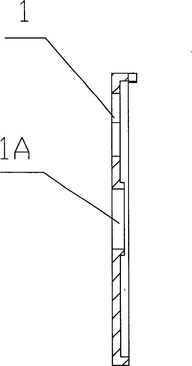
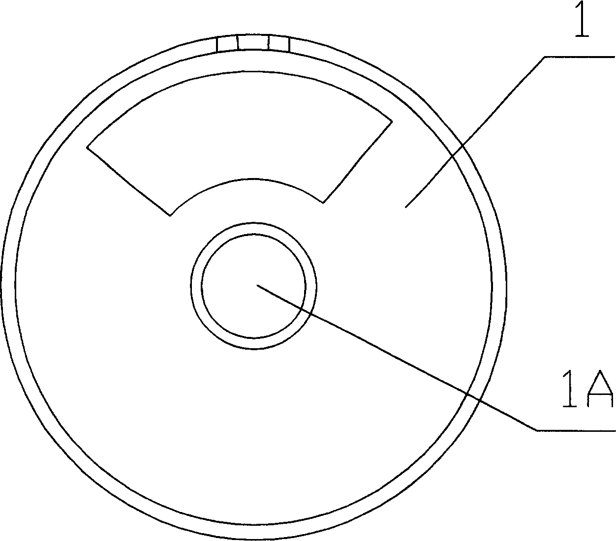
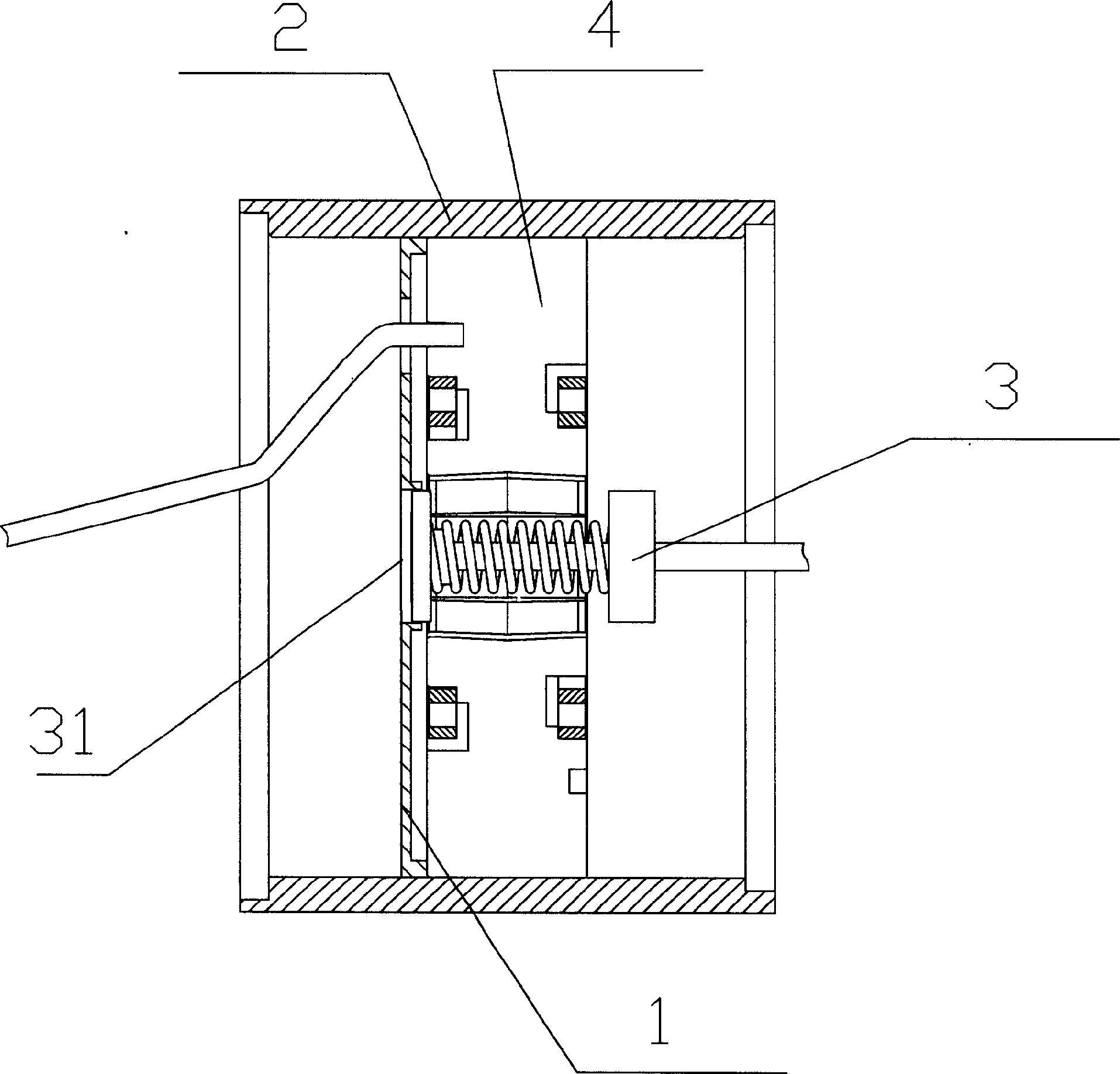
[0015] The present invention is used for the welding jig of vacuum tube, and the outer diameter of the jig 1 made of heat-conducting insulating material is consistent with the inner diameter of the anode cylinder 2, and the middle part of the jig 1 is provided with a through hole 1A concentric with its outer diameter, and the diameter of the through hole 1A is the same as the inner diameter of the anode cylinder 2. The outer diameters of the shielding covers 31 in the filament assembly 3 are consistent.

[0016] The present invention uses above-mentioned welding jig 1 to carry out the method for vacuum tube welding, comprises the following steps:

[0017] 1) Put the clamp 1 whose outer diameter is consistent with the inner diameter of the anode cylinder 2 in the anode cylinder 2;

[0018] 2) Put the shielding cover 31 in the filament assembly 3 into the through hole 1A provided in the middle of the fixture 1 and concentric with its outer diameter;

[0019] 3) Welding the fila...


PUM


Abstract

The present invention relates to one kind of welding fixture and welding method for vacuum tube. The welding fixture made of heat conducting and electric insulating material has outer diameter equal to the inner diameter of the anode tube, and coaxial through hole in the middle part in the diameter equal to the outer diameter of the shielding cover of the filament assembly. The vacuum tube welding method with the welding fixture includes the following steps: 1. setting the fixture inside the anode tube; 2. setting the shielding cover of the filament assembly inside the through hole; and 3. welding the filament assembly coaxially with the anode tube. The fixture of the present invention has simple structure, and the welding method is simple, high in efficiency and low in cost, and can ensure the use performance of the vacuum tube.

Description

1. Technical field: [0001] The invention relates to a welding jig for a vacuum tube and a welding method thereof, and belongs to the innovative technology of the welding jig and the welding method for the vacuum tube. 2. Background technology: [0002] In the process of vacuum tube production, the welding of the filament assembly is performed by the production workers based on their experience. The disadvantage is that the filament assembly is likely to be not on the same axis as the anode cylinder after welding, resulting in the eccentricity of the vacuum tube and even affecting the vacuum tube. When the performance is serious, it needs to be repaired or the vacuum tube is scrapped, which not only wastes manpower and material resources, increases production cost, but also affects production efficiency. 3. Contents of the invention: [0003] The object of the present invention is to provide a welding jig for vacuum tubes with a simple structure in consideration of the abov...

Claims


Application Information

Patent Timeline
Patent Type & Authority Applications(China)
IPC IPC(8): B23K37/053
Inventor 彭韶斌
Owner GUANGDONG WITOL VACUUM ELECTRONICS MFR
Why Eureka
Try Eureka