Moulding apparatus and method for producing optical component
A technology of compression molding and optical components, which is applied in the field of compression molding equipment and forming material supply, which can solve the problems of non-circular shape, difficulty in correcting the position of forming materials, and biting of forming materials into side molds, etc., and achieve the effect of high efficiency and surface accuracy
- Summary
- Abstract
- Description
- Claims
- Application Information
AI Technical Summary
Problems solved by technology
Method used
Image

Examples
no. 1 approach
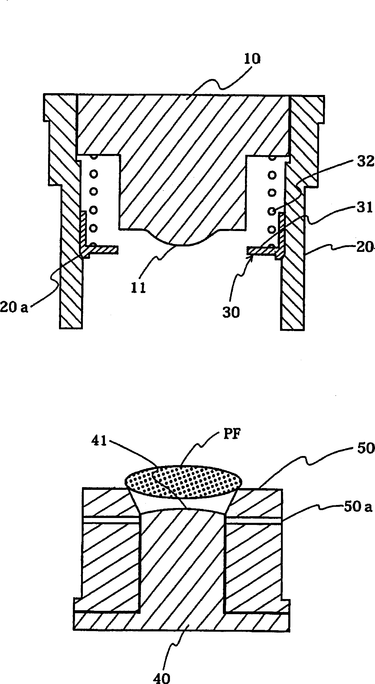
[0074] First, regarding the compression molding apparatus (hereinafter referred to as molding apparatus) according to the first embodiment of the present invention, refer to figure 1 Be explained.
[0075] figure 1 It is a sectional view of main parts of the press molding apparatus according to the first embodiment of the present invention.
[0076] Also, although not shown, the molding device of this embodiment includes a heating device and a temperature adjustment mechanism necessary for heating a molding device and / or a molding material, a load applying shaft mechanism having a load adjustment mechanism necessary for press molding, There is also a cooling device and a temperature adjustment mechanism necessary for the cooling of the forming device and / or the formed body.
[0077] In addition, during pressing, the upper end surface of the upper die and the lower end face of the lower die contact the press forming shaft of the load applying shaft mechanism to apply a load...
no. 2 approach
[0112] Next, regarding the molding device and the method of manufacturing an optical element using the molding device according to the second embodiment of the present invention, refer to Figure 5 and Image 6 Be explained. Note that the same reference numerals as in the first embodiment are assigned to the same configuration as the first embodiment, and the description of the first embodiment is continued.
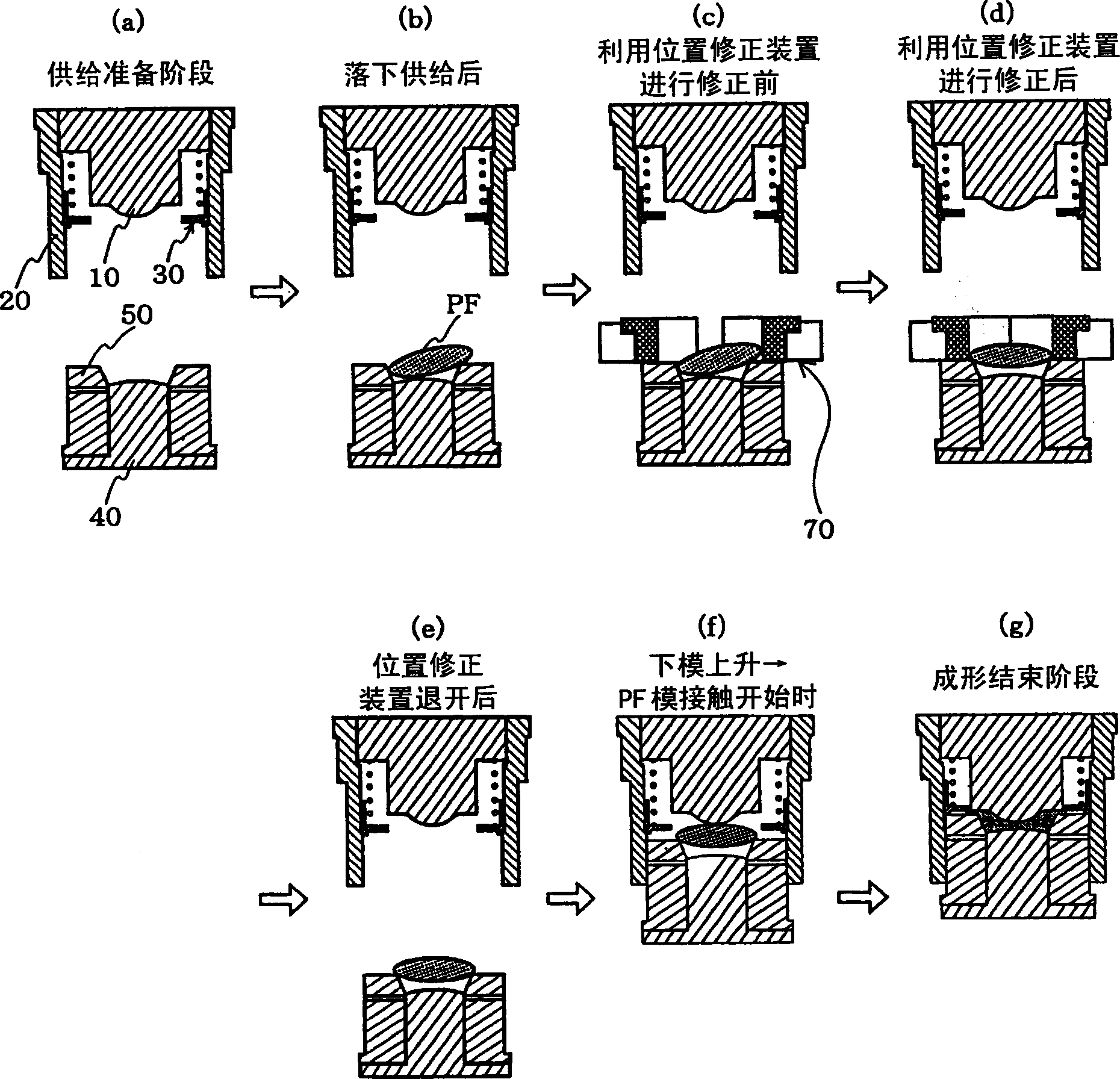
[0113] Figure 5 is a sectional view of main parts of a press molding apparatus according to a second embodiment of the present invention, Image 6 It is an explanatory drawing showing the manufacturing process of the optical element by the shaping|molding apparatus of 2nd Embodiment.
[0114]The molding device of the second embodiment is also composed of an upper mold 10, an upper side mold 20, a forced demoulding device 30, a lower mold 40, and a lower ring 51 as a supporting member. However, a lower side surrounding the lower ring 51 is also provided. Modulus 80. ...
no. 3 approach
[0124] Next, regarding the molding device according to the third embodiment of the present invention and the method of manufacturing an optical element using the molding device, refer to Figure 7 and Figure 8 Be explained.
[0125] Figure 7 is a sectional view of main parts of a compression molding apparatus according to a third embodiment of the present invention, Figure 8 It is an explanatory drawing showing the manufacturing process of the optical element by the shaping|molding apparatus of 3rd Embodiment.
[0126] Figure 8 The steps shown are the same as those representing the manufacturing steps performed by the manufacturing apparatus of the above-mentioned second embodiment. Image 6 Corresponding to each process. The forming device of the third embodiment has the same structure as that of the second embodiment. As the upper and lower dies 10, 40 move closer, the lower ring 51 retreats below the forming surface of the lower die. However, it is different from t...
PUM
 Abstract
Description
Claims
Application Information
 - R&D Engineer
- R&D Manager
- IP Professional
- Industry Leading Data Capabilities
- Powerful AI technology
- Patent DNA Extraction
Browse by: Latest US Patents, China's latest patents, Technical Efficacy Thesaurus, Application Domain, Technology Topic.
© 2024 PatSnap. All rights reserved.Legal|Privacy policy|Modern Slavery Act Transparency Statement|Sitemap