Thermal transfer printer

A printing press and thermal transfer technology, applied in printing, inking device and other directions, can solve the problems of longer size B, higher image printing costs, and higher operating costs, and achieve size reduction, low printing costs, and reduced operating costs. Effect

Inactive Publication Date: 2006-05-24
ALPS ALPINE CO LTD
View PDF1 Cites 5 Cited by
  • Summary
  • Abstract
  • Description
  • Claims
  • Application Information

AI Technical Summary

Problems solved by technology

[0023] However, in the conventional thermal transfer printing machine 31, the belt sensor 42 is set in the retreat groove 39d of the tape cassette 39 separated from the heating element of the thermal head 33, so it is connected with the heating element of the thermal head 33 to the belt. The dimension B of the gap portion 38d of the ink ribbon 38 corresponding to the dimension of the sensor 42 becomes longer.
[0024] Therefore, the portion of the ink ribbon 38 that is not supplied for printing is increased, and the running cost is increased, and there is a problem that the image printing cost per sheet of the recording paper 34 becomes high.

Method used


Image

  • Thermal transfer printer
  • Thermal transfer printer
  • Thermal transfer printer

Examples


Embodiment Construction

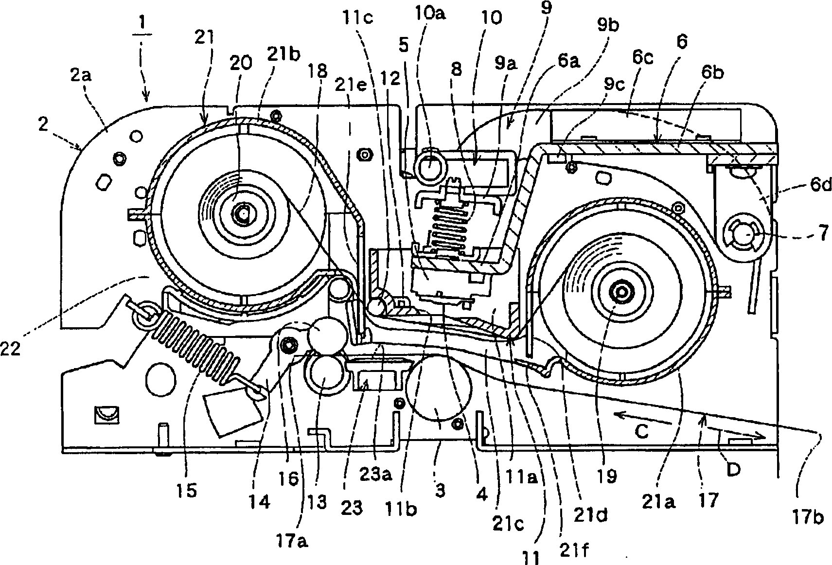
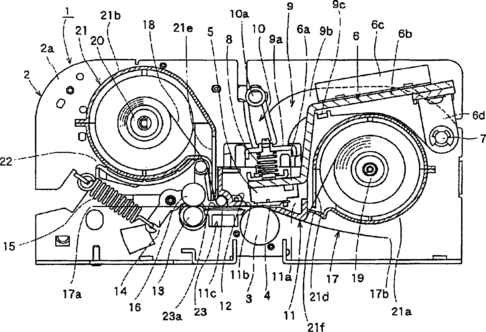
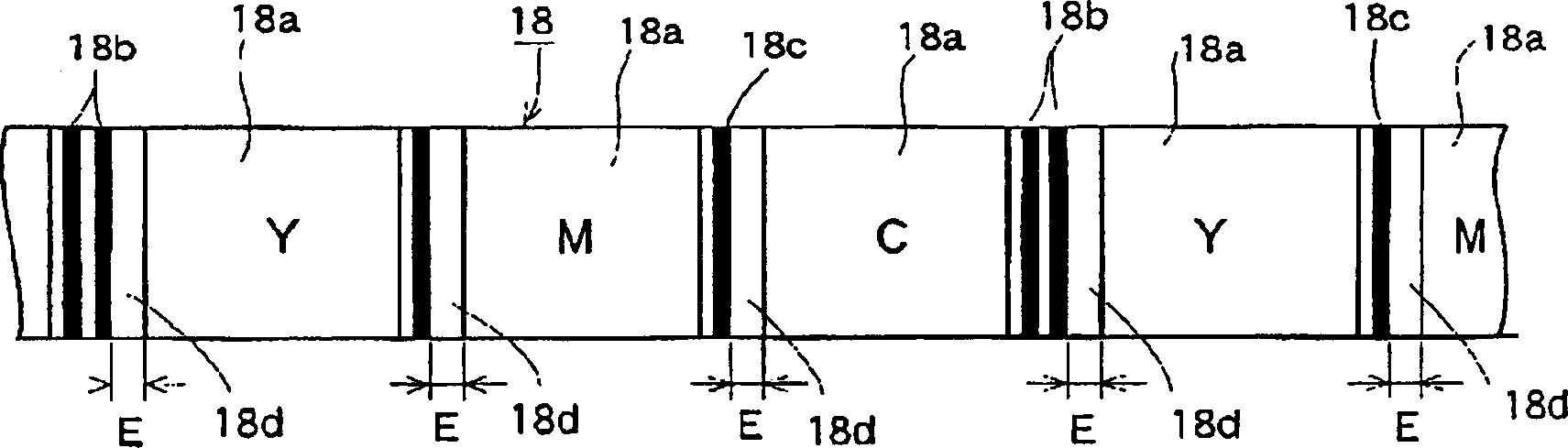
[0042] Below, with reference to the accompanying drawings, according to Figure 1 ~ Figure 3 One embodiment of the thermal transfer printer of the present invention will be described. figure 1 , figure 2 It is a sectional view of main parts of the thermal transfer printing machine of the present invention, image 3 It is a plan view of the ink ribbon of the present invention.

[0043] like figure 1 In the shown thermal transfer printing machine 1 , a cylindrical platen roller 3 , which is rotatably supported by a side plate 2 a of the main body cover 2 , is provided on the lower side.

[0044] A thermal head 4 composed of a long linear head parallel to the axial direction of the platen roller 3 is provided above the platen roller 3 .

[0045] The thermal head 4 has a plurality of heating elements (not shown) aligned and aligned in the longitudinal direction on the side opposite to the platen roller 3 , and is mounted on the head support member 6 through the head mounting ...


PUM


Abstract

The purpose of the present invention is to provide a thermal transfer printing machine that reduces the running cost of the ink ribbon and can reduce the image cost of each piece of recording paper. It is characterized in that it has: a thermal head (4), which can The platen roller (3) that lifts / falls the head of the thermal head (4), and the ink ribbon (18) that leads between the thermal head (4) and the platen roller (3) can transport and record Paper feeding roller (13) of paper (17); on the downstream side of the thermal head (4) in the conveying direction of recording paper (17), it is provided with a roller that can be in close contact with recording paper (17) during printing. The peeling roller (11c) that peels off the ink ribbon (18) is provided between the thermal head (4) and the peeling roller (11). The corresponding detection marker detects the optical type belt sensor (12).

Description

technical field [0001] The invention relates to a thermal transfer printer, in particular to a thermal transfer printer which can reduce the running cost of the ink ribbon. Background technique [0002] According to the invention described in Japanese Patent Document 1, a conventional thermal transfer printing machine 31 is described, such as Figure 4 As shown, the thermal transfer printer 31 has a printer body 31a and a cassette mounting portion 31b in which a tape cassette 39 described later can be mounted in the printer body 31a. [0003] In addition, a platen roller 32 is provided inside the printer main body portion 31 a, and a thermal head 33 is provided above the platen roller 32 . [0004] Further, between the thermal head 33 and the platen roller 32 , the recording paper 34 is fed and conveyed. [0005] The thermal head 33 is supported by a print head mount 35 mounted on a print head rod 36 . Further, the head lever 36 is rotatably supported with the support shaf...

Claims


Application Information

Patent Timeline
Patent Type & Authority Applications(China)
IPC IPC(8): B41J2/32B41J33/14
CPCB41J2/325B41J35/18
Inventor 丸山贵史阿部荣文
Owner ALPS ALPINE CO LTD
Why Eureka
Try Eureka