


Quick Research
Generate reliable direction feasibility study reports for your R&D in just a few steps.

Technical Q&A
Discover and master advanced knowledge NOW. Basics, ideas, possibilities, all at once.

Find Solutions
As an expert in R&D theories, this can generate solutions to your technical problems instantly.

Evaluate Feasibility
Analyze your overall solution with one click, know your potential R&D risks in advance.

Monitor Landscape
Get weekly tech updates, stay abreast of the latest tech innovations and key insights.
Sea water electric field
A seawater and electric field technology, applied in ocean energy power generation, engine components, machines/engines, etc.
- Summary
- Abstract
- Description
- Claims
- Application Information
AI Technical Summary
Problems solved by technology
Method used
Image

Examples
Embodiment Construction
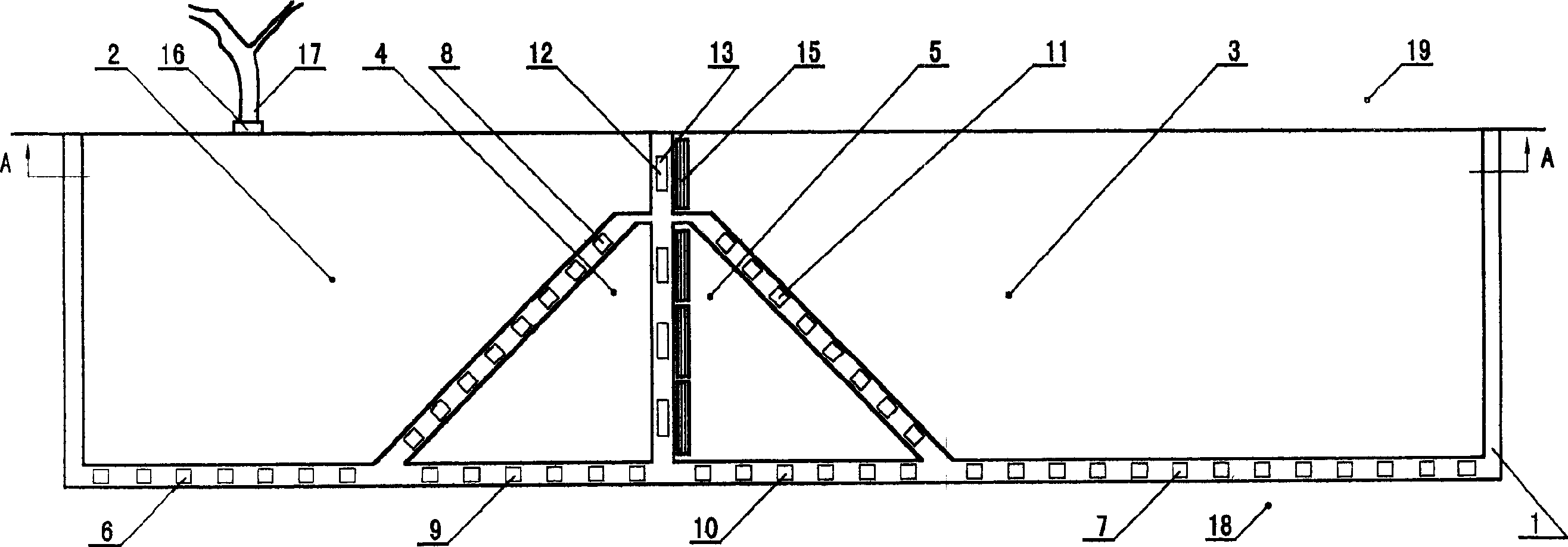
[0044] First open all the gate groups, until the tide is flat, the sea level is at the zero level of the sea level, and the water levels of the reservoir areas A and B, as well as the water inlet and outlet control areas are also at the zero level of the sea level. At this time, close the B, E, F and G gate groups so that the B reservoir area is at the water level of 0 level of the sea level. The sea water starts to rise, and the water level in reservoir area A rises with the sea water. When the sea water rises to 3 meters above the sea level, it can generate electricity. For the sake of clarity, when this is used as a starting point, a tidal change cycle is divided into several periods to describe the implementation process of producing electric energy.
[0045] The first period (see Figure 4): When the sea water rises to 3 meters above the sea level (at this time, the water level in reservoir A = 3 meters above the sea level, and the water level in reservoir B = 0 at the s...
PUM
 Abstract
Description
Claims
Application Information
 - R&D Engineer
- R&D Manager
- IP Professional
- Industry Leading Data Capabilities
- Powerful AI technology
- Patent DNA Extraction
Browse by: Latest US Patents, China's latest patents, Technical Efficacy Thesaurus, Application Domain, Technology Topic, Popular Technical Reports.
© 2024 PatSnap. All rights reserved.Legal|Privacy policy|Modern Slavery Act Transparency Statement|Sitemap|About US| Contact US: help@patsnap.com