
Method and heating furnace for controlling product temperature evenness in metallurgical heating furnace

A heating furnace and uniformity technology, applied in the field of temperature uniformity control, can solve problems such as unfavorable and unfavorable burner good efficiency, and achieve the effect of improving temperature uniformity and reducing the existence of hot spots

Inactive Publication Date: 2010-08-18
STEIN-HEURTEY
View PDF3 Cites 0 Cited by
  • Summary
  • Abstract
  • Description
  • Claims
  • Application Information

AI Technical Summary

Problems solved by technology

This is not conducive to good efficiency of the burner, nor to an even temperature

Method used


Image

  • Method and heating furnace for controlling product temperature evenness in metallurgical heating furnace
  • Method and heating furnace for controlling product temperature evenness in metallurgical heating furnace
  • Method and heating furnace for controlling product temperature evenness in metallurgical heating furnace

Examples


Embodiment Construction

[0039] Referring to FIG. 1 , a heating furnace consisting of an insulated furnace chamber 1 can be seen schematically. A product 2 to be heated is supported in the heating furnace by a support beam 3 and moved from right to left in the figure by a mechanism 4 . Spread flame burners 5 are located on the side walls of the furnace above and below the product 2 bed.

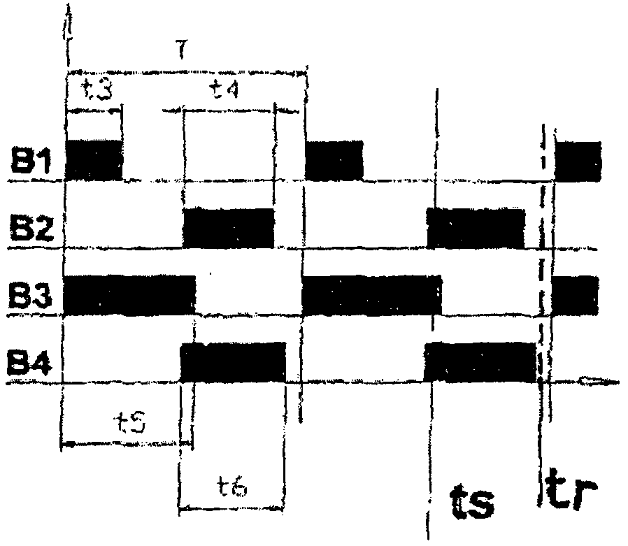
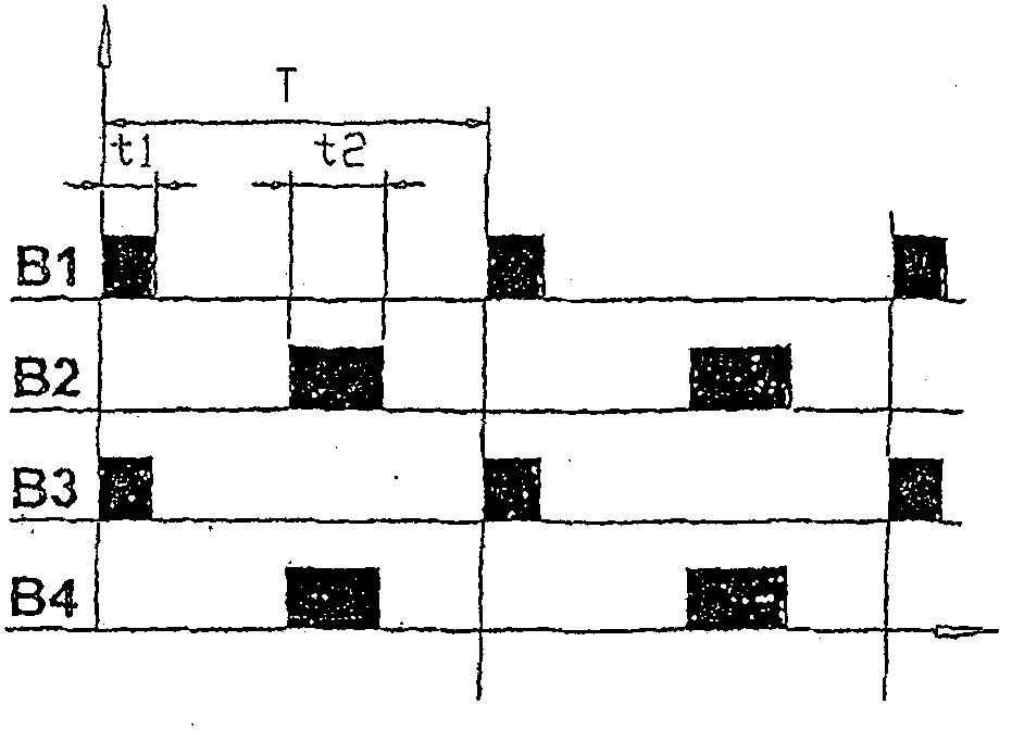
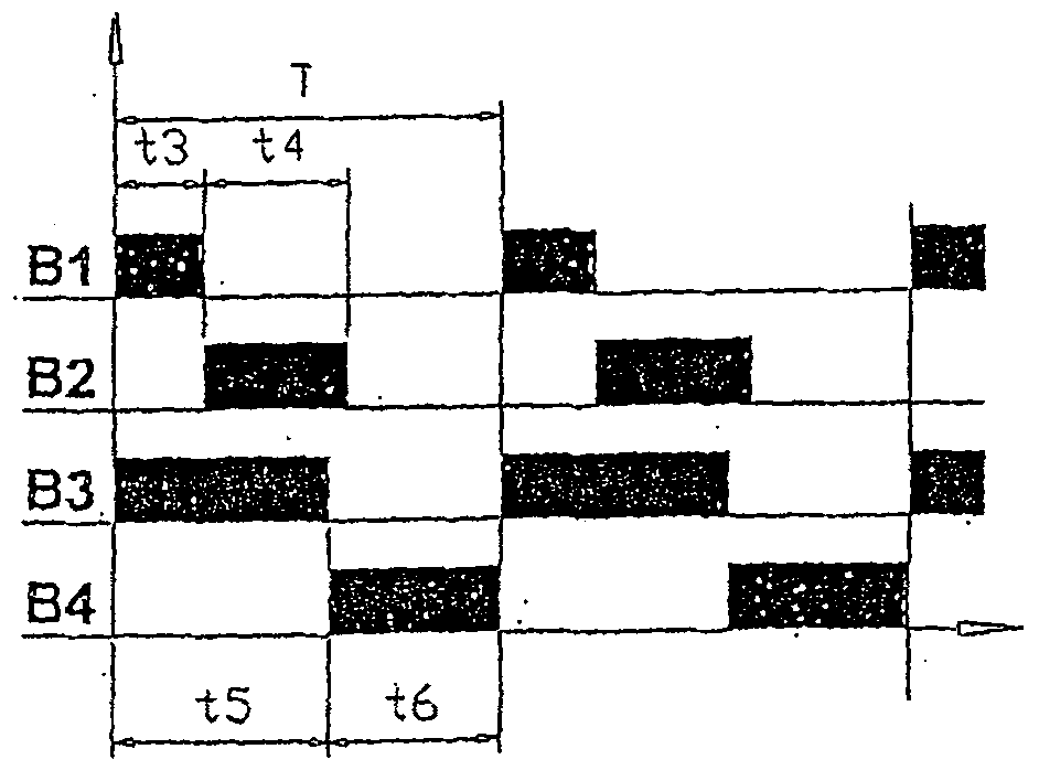
[0040] Figure 2 schematically shows a spread-flame burner provided with a combustion channel 6 of widened (élargie) shape, L at least equal to 1.3 times H, and having some long axis of symmetry PS with the channel and located in the furnace The plane P of the product is parallel to the fuel injection nozzle 8 and the oxidizer nozzle 7 . The direction of the fuel and oxidant injection nozzles is chosen so as to produce a poor distribution of combustion products and circulating flue gases in order to obtain a spreading flame that ensures a uniform distribution of heat flux.

[0041]An example of a furnace according to...


PUM


Abstract

The invention aims to reduce the dimension of a heater along with the longitudinal direction of a fluid chamber, fluid input and output pipe castings (5,6) bulging on a front surface (F1) of the heater are on the point where an angle is formed with the vertical axis line (A1,A2) of the fluid chamber (1,2).

Description

technical field [0001] The invention relates to a method for controlling the temperature uniformity of a metallurgical product, in particular a blooming slab or billette, in a furnace equipped with lateral burners. Background technique [0002] The function of the metallurgical heating furnace is to bring the product to a given rolling temperature, and all points of the product have good temperature uniformity. [0003] The heating of the furnace is traditionally achieved by means of burners, which are supplied with air and fossil fuel and are mounted on the furnace wall. Burners are characterized by their power and flame shape for different operating regimes, depending on their design, and the pressure and flow of fuel and oxidizer. Flames generally have a characteristic thermal profile characterized by the presence of a hot spot where a significant portion of the released energy and radiation is concentrated. Controlling the position of the hot spot of the flame is not a...

Claims


Application Information

Patent Timeline
Patent Type & Authority Patents(China)
IPC IPC(8): F27B9/36
CPCF27B9/36
Inventor A·莫雷尔
Owner STEIN-HEURTEY
Learn More