Pulse width modulator with automatic change of outputting frequency

A pulse width modulation and output frequency technology, applied in the direction of output power conversion device, AC power input conversion to DC power output, electrical components, etc., can solve problems such as entering the shutdown state, controlling IC shutdown or output instability

Inactive Publication Date: 2006-05-31
NIKO SEMICON
View PDF0 Cites 21 Cited by
  • Summary
  • Abstract
  • Description
  • Claims
  • Application Information

AI Technical Summary

Problems solved by technology

However, this power saving method will make the load sleep under light load or no load, and may even enter the shutdown state, resulting in unwanted shutdown of the control IC or output instability

Method used


Image

  • Pulse width modulator with automatic change of outputting frequency
  • Pulse width modulator with automatic change of outputting frequency
  • Pulse width modulator with automatic change of outputting frequency

Examples


Embodiment Construction

[0063] Please refer to Figure 7 , is a schematic circuit block diagram of the pulse width modulation device of the present invention. The pulse width modulation device 3 of the present invention can follow the load change of the power supply, thereby changing the frequency of the output drive signal, including: a hysteresis comparison circuit 32, a signal synchronization circuit 33, a dual-frequency oscillator 34 and a PWM control Device 36.

[0064] please refer again Figure 7 , the present invention receives a feedback voltage V at the load end of the power supply FB At the same time, a certain current source CIS is used to transmit power to two series-connected first resistors R1 and second resistors R2, and the two series-connected resistors R1 and R2 are used to divide the power to obtain a A high threshold voltage VH and a low threshold voltage VL. Afterwards, the hysteresis comparison circuit 32 intercepts the feedback voltage V FB . The high critical voltage VH ...


PUM


Abstract

A PWM device able to automatically change output frequency according to load variation of power supply is composed of a delay comparator for comparing between feedback voltage, high critical voltage and low critical voltage and performing delay operation to output frequency varying signal A, a signal synchronizer for receiving signal A and outputting a power-saving enable signal B, a dual-frequency oscillator for receiving signal B and outputting relative oscillation frequency, and a PWM controller for receiving the oscillation frequency and outputting a drive signal.

Description

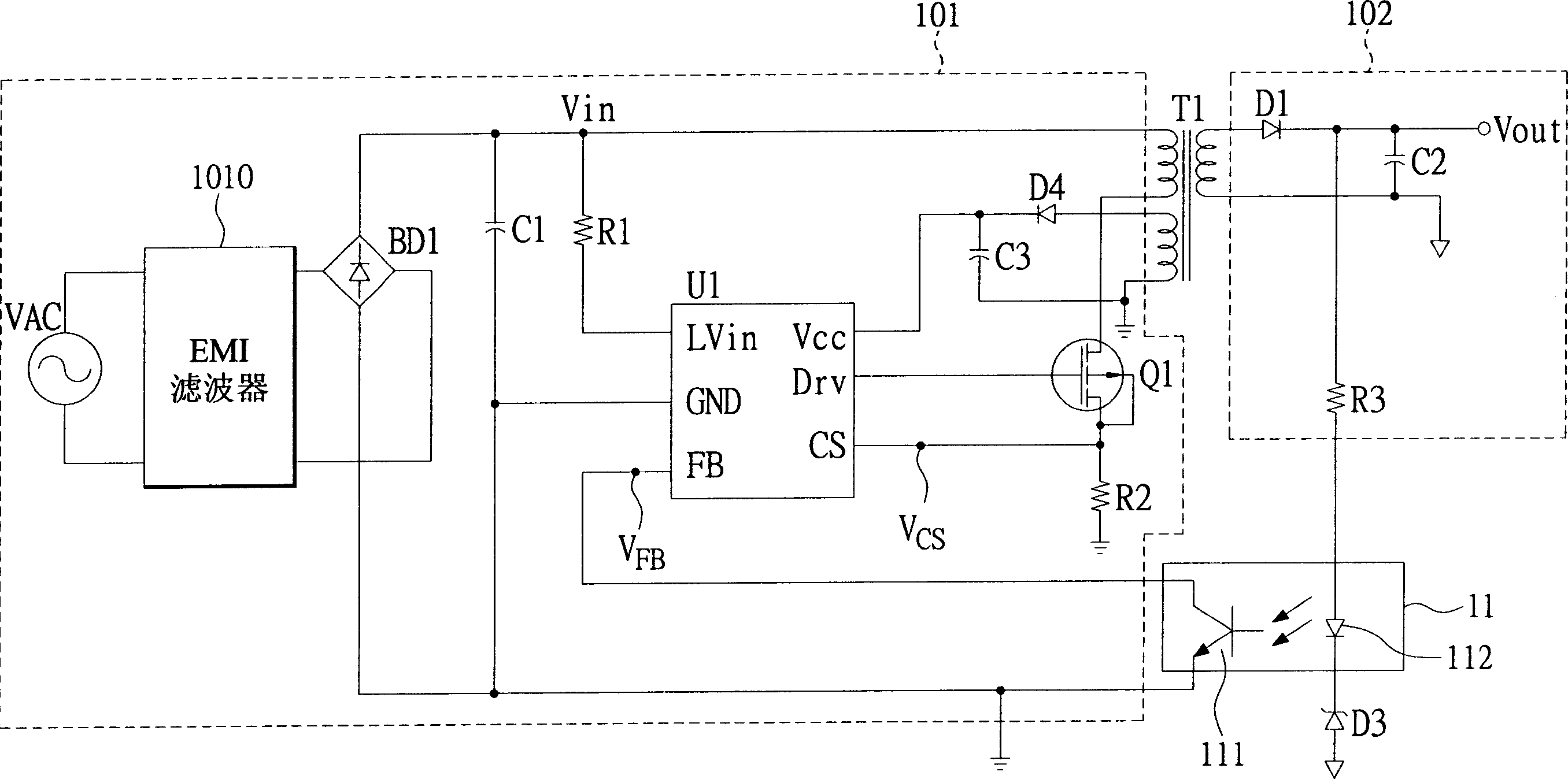
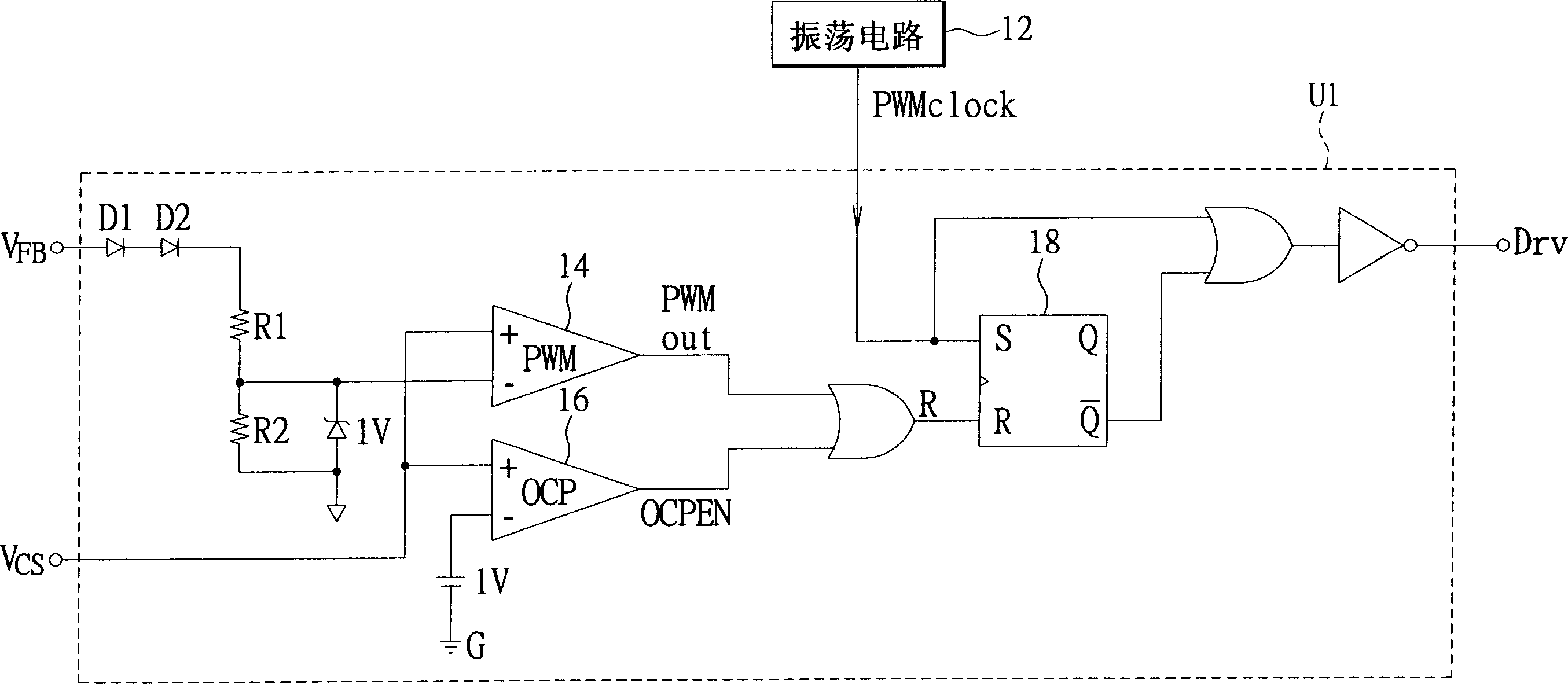
technical field [0001] The present invention relates to a pulse width modulation device that automatically changes the output frequency, in particular to a pulse width modulation device used in a power supply to change the output switching frequency by following the load change. Background technique [0002] In many low-power output applications, such as chargers for mobile phones, wireless phones, digital cameras, and PDAs, as well as AC voltage regulators for printers, video games, and handheld players, the requirements for power saving during standby are quite high . [0003] According to the currently known DC power supply devices, such as AC To DCSwitching Power Supply, in order to reduce the size of the transformer, most of them use high-frequency pulse width modulation (PWM) to control the DC output voltage, such as figure 1 As shown, it is a schematic circuit diagram of an existing flyback power supply device. The transformer T1 divides the circuit into a primary-si...

Claims


Application Information

Patent Timeline
Patent Type & Authority Applications(China)
IPC IPC(8): H02M7/00
Inventor 吴俊政
Owner NIKO SEMICON
Why Eureka
Try Eureka