
Controller

A technology of control device and driven body, applied in automatic control device, feeding device, program control, etc., can solve the problems of vibration, reduction of machining accuracy, difficulty in setting waiting time, etc., to achieve stable operation control, improve machining Precision, no time-wasting effect

Inactive Publication Date: 2006-06-07
FANUC LTD
View PDF1 Cites 9 Cited by
  • Summary
  • Abstract
  • Description
  • Claims
  • Application Information

AI Technical Summary

Problems solved by technology

[0006] In the case where the next operation after the positioning operation of the driven body in rapid feed is a processing operation such as cutting or tool replacement, etc., wait for the specified waiting time before the vibration stops and the state becomes stable before transferring to It is difficult to set the waiting time in the conventional method of the next cutting process or changing the tool
If the waiting time is long, the overall processing time will be longer. Conversely, if the waiting time is short, the cutting operation or tool replacement operation will be performed while the driven body (workpiece, table, tool, etc.) It is difficult to set the most appropriate waiting time for the desired machining accuracy or the impossibility of normal tool replacement.
[0007] In addition, in the execution of machining operations such as cutting, if there is a sudden speed change, vibration may also occur on the driven body, which will reduce the machining accuracy.

Method used


Image

  • Controller
  • Controller
  • Controller

Examples


Embodiment Construction

[0032] An example in which the present invention is applied to a numerical control device as a control device for a machine tool will be described below.

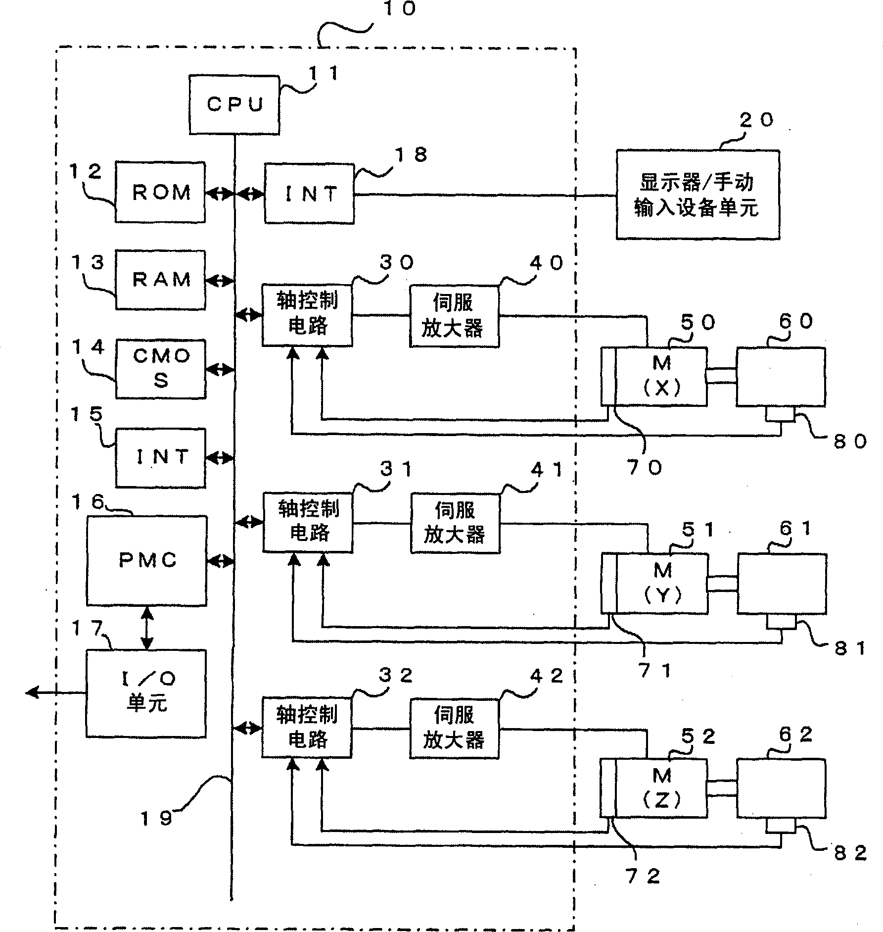
[0033] figure 1 is a block diagram of main units of the control device of the present invention. The CPU 11 is a processor that controls the control device 10 that performs numerical control as a whole. The CPU 11 reads the system program stored in the ROM 12 through the bus 19, and controls the entire control device in accordance with the system program. Calculation data or display data and various data input by the operator through the display / manual input device unit 20 composed of a display made of a CRT or liquid crystal and a keyboard or the like are temporarily stored in the RAM 13 Composition of manual input devices. The CMOS memory 14 is backed up by a battery (not shown), and is configured as a nonvolatile memory capable of maintaining a stored state even when the power of the control device 10 is turned off. ...


PUM


Abstract

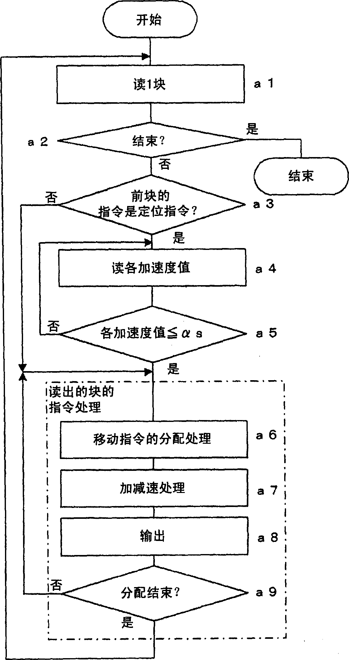
An acceleration detection unit for detecting acceleration is mounted on the driven body. When the previous block is a positioning command, after the distribution of the movement command of the positioning command is completed, wait until the acceleration detection value detected by the acceleration detection means becomes less than or equal to αs. When the acceleration detection value becomes equal to or less than αs, distribution of the movement command for the next block starts. Since the cutting feed starts after the acceleration detection value becomes equal to or less than αs and the vibration stops, high-precision machining is possible.

Description

technical field [0001] The present invention relates to a control device for controlling the position and / or speed of a driven body in a processing machine such as a machine tool. Background technique [0002] In a processing machine such as a machine tool, processing is performed by moving a tool such as a cutter relative to a workpiece to be processed. In order to control the processing position or speed, the driven body (the workpiece, the worktable on which the workpiece is installed, or tools such as tools) is driven by a servo motor, and position feedback, speed feedback, and current feedback control are usually performed to control the position or speed of the driven body. control. [0003] Through the feedback control of the position, speed, and current, the machining position, speed, machining torque, etc. are controlled. However, when the speed and acceleration of the driven body change suddenly, sometimes the sharp change will cause damage to the driven body. Vi...

Claims


Application Information

Patent Timeline
Patent Type & Authority Applications(China)
IPC IPC(8): B23Q15/00B23Q5/22B23Q15/20B23Q17/10B23Q17/12B23Q17/22G05B19/4155
CPCG05B19/416G05B2219/37388G05B2219/43058Y10T483/1702Y10T483/1733
Inventor 岩下平辅置田肇河村宏之猪饲聪史
Owner FANUC LTD
Learn More