Equipment and method for manufacturing a glass preform
一种预型体、玻璃的技术,应用在制造工具、玻璃生产、玻璃制造设备等方向,能够解决昂贵等问题
Active Publication Date: 2010-12-01
SUMITOMO ELECTRIC IND LTD
View PDF3 Cites 0 Cited by
- Summary
- Abstract
- Description
- Claims
- Application Information
AI Technical Summary
Problems solved by technology
However, due to the need for an extrusion and a pneumatic mechanism for extruding the extrusion, sealing gas supplied to the passage between the extrusion and the flange, and a supply and discharge device for the sealing gas, etc., the required The equipment is relatively large, and it is expensive to provide such large equipment
Method used
View moreImage
Smart ImageViewing Examples
Examples
Embodiment Construction
Login to View More PUM
| Property | Measurement | Unit |
|---|---|---|
| roughness | aaaaa | aaaaa |
| surface smoothness | aaaaa | aaaaa |
| diameter | aaaaa | aaaaa |
Abstract
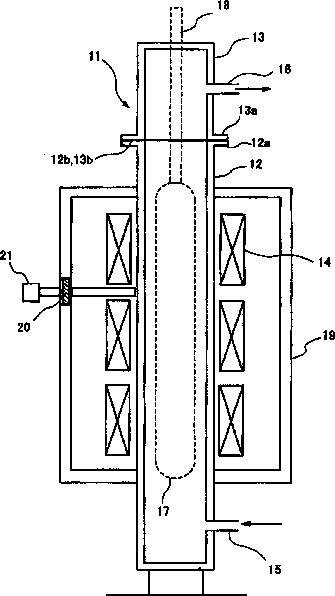
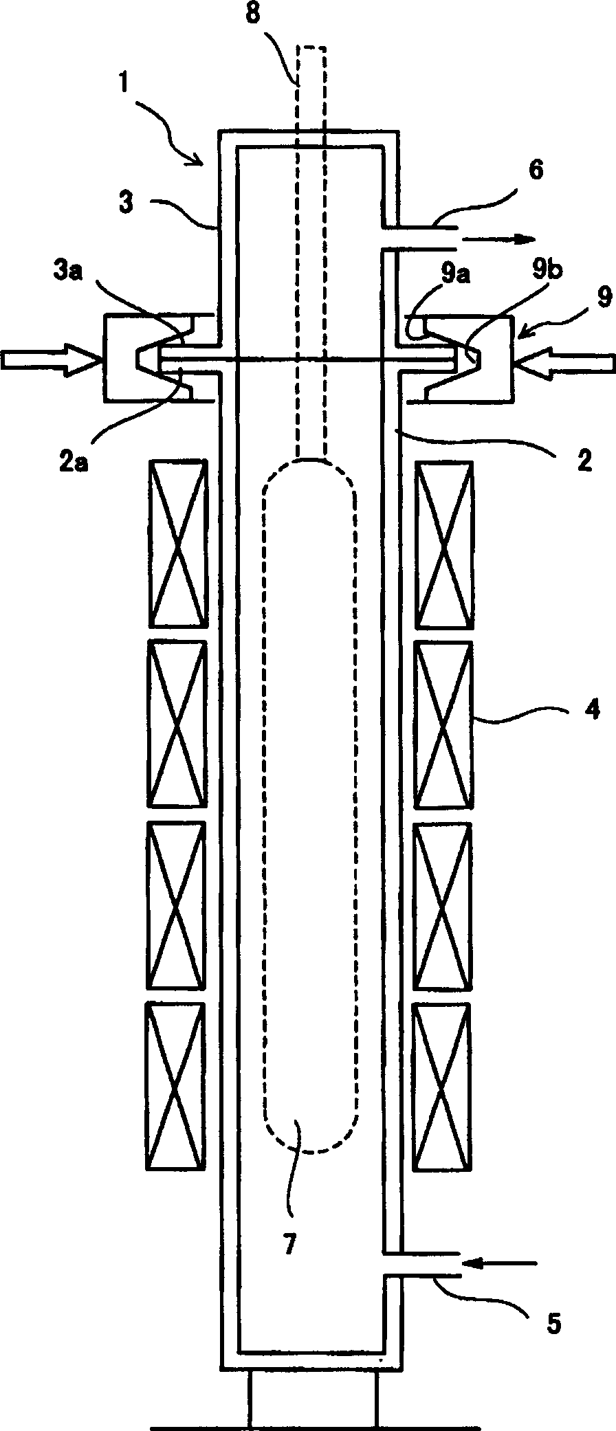
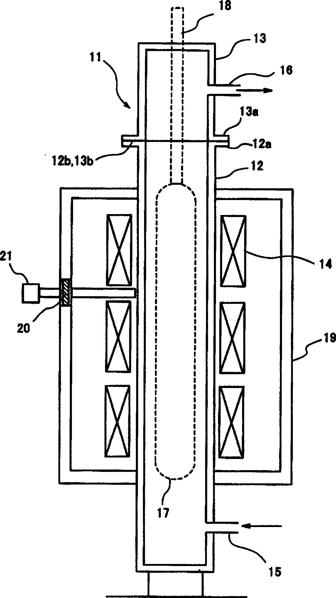
Provide are safe equipment and method, in which gas leakage through junction part between a furnace muffle tube and a lid can be restrained, for manufacturing a high quality glass preform. The equipment for manufacturing a glass preform comprises (1) a furnace muffle tube in which a soot glass deposit body is placed, (2) a lid for sealing up an inlet-outlet opening of the furnace muffle tube, and(3) a heater for heating the soot glass deposit body. The method of producing a soot glass deposit body comprises steps of (1) placing a soot glass deposit body into a furnace muffle tube, (2) sealing up the inlet-outlet opening of the furnace muffle tube with a lid, (3) heating the soot glass deposit body so as to vitrify it into a transparent glass body. In these equipment and the method, the surface roughness in the respective junction surfaces of the furnace muffle tube and the lid is 1.0 mum or less, the flatness degree in the respective junction surfaces of the furnace muffle tube and the lid is 30 mum or less, and the load on the junction surface is equal to or more than 98 N.
Description
Apparatus and method for manufacturing glass preform Technical field The present invention relates to an apparatus and method for manufacturing a glass preform, which vitrifies a glass particle deposit body into transparent glass by dehydrating and sintering it to manufacture a glass preform. Background technique In a known method of manufacturing a glass preform for an optical fiber, a glass particle deposit is first manufactured, and then it is vitrified into transparent glass by dehydration and sintering. In some cases, the glass preform is softened by heating and elongated so that it has a given outer diameter. Vapor axial deposition method (VAD method), external vapor deposition method (OVD method), etc. are well-known methods for manufacturing glass particle deposits. In these methods, fine glass particles obtained by flame-hydrolysis of glass raw material gases such as SiCl4 and GeCl4 are deposited on a starting glass rod, thereby obtaining a glass particle deposit. I...
Claims
Login to View More Application Information
Patent Timeline
 Patent Type & Authority Patents(China)
IPC IPC(8): C03B37/014C03B37/018G02B6/00
CPCC03B37/0146C03B37/01406Y02P40/57
Inventor 石原朋浩守屋知己
Owner SUMITOMO ELECTRIC IND LTD
- R&D Engineer
- R&D Manager
- IP Professional
- Industry Leading Data Capabilities
- Powerful AI technology
- Patent DNA Extraction
Learn More Browse by: Latest US Patents, China's latest patents, Technical Efficacy Thesaurus, Application Domain, Technology Topic, Popular Technical Reports.
© 2024 PatSnap. All rights reserved.Legal|Privacy policy|Modern Slavery Act Transparency Statement|Sitemap|About US| Contact US: help@patsnap.com


