Antenna earthing structure

A technology of antenna and ground plane, applied in the direction of antenna grounding device, etc., can solve the problem of inability to adjust electrical characteristics, and achieve the effect of improving the manufacturing process and good electrical characteristics

Inactive Publication Date: 2006-06-07
AMPHENOL EAST ASIA TAIWAN BRANCH
View PDF0 Cites 4 Cited by
  • Summary
  • Abstract
  • Description
  • Claims
  • Application Information

AI Technical Summary

Problems solved by technology

[0004] However, this grounding method still needs to connect the grounded metal plate with the metal frame of the

Method used


Image

  • Antenna earthing structure
  • Antenna earthing structure
  • Antenna earthing structure

Examples


Embodiment approach

[0016] In order to enable the examiner to have a further understanding and understanding of the structural features and the achieved effects of the present invention, I would like to provide a preferred embodiment and a detailed description, as follows:

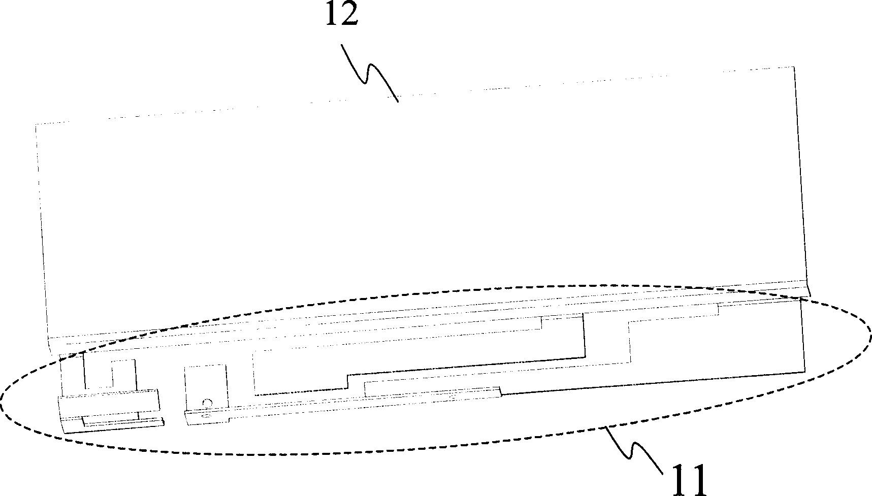
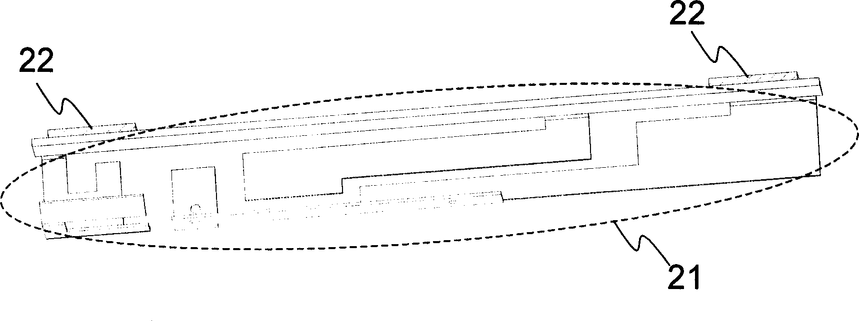
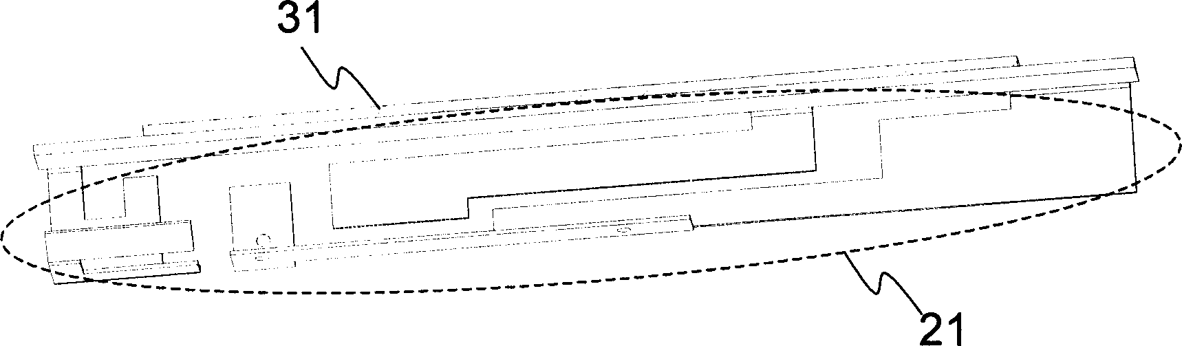
[0017] see figure 2 , is a schematic diagram of an embodiment of the antenna grounding structure of the present invention. The antenna grounding structure is used for an electronic device such as a portable computer, and includes an antenna body 21 and a conductive plastic 22 .

[0018] The antenna body 21 includes at least a radiating element operating in at least one frequency band and a ground plane. Generally, the antenna body 21 can be made of metal, and the operable frequency bands can be wireless radios such as GSM850, GSM900, DCS1800, PCS1900, UMTS, and WLAN. Communication frequency band.

[0019] The conductive plastic 22 is used to connect the antenna body 21 on the metal frame of the electronic device. The condu...


PUM


Abstract

This invention relates to an antenna earth structure used in electronic devices including an antenna and conducting plastics, in which, the antenna is connected to the metal frame of an electronic device by the conducting plastics to provide fine electric property and improve the flow of manufacturing.

Description

Technical field: [0001] The invention relates to an antenna grounding structure, which is used in electronic devices, and in particular relates to using conductive foam to ground the antenna body. Background technique: [0002] The use of personal computers is very common at present, such as portable computers in personal computers, because of its small size and light weight, it is suitable for carrying around for document processing. In addition, with the development of wireless communication technology, it is no longer necessary to use a network line as a physical connection for data transmission. Instead, an antenna can be installed on a portable computer to achieve the function of transmitting or receiving data through the antenna. . Therefore, in the process of wireless communication, the main component antenna plays a very important role. In general wireless communication systems, the role of the antenna is to transmit and receive electromagnetic wave energy. Whether ...

Claims


Application Information

Patent Timeline
IPC IPC(8): H01Q1/48
Inventor 王秋水魏永昌
Owner AMPHENOL EAST ASIA TAIWAN BRANCH
Why Eureka
Try Eureka