
Magnetoresistive sensor, comprising a ferromagnetic/antiferromagnetic sensitive element

A technology of magnetoresistance and sensitive element, applied in the field of magnetoresistance magnetic field sensor, which can solve the problems of structure loss and poor barrier.

Inactive Publication Date: 2006-06-07
S.N.R.鲁尔门斯公司
View PDF1 Cites 4 Cited by
  • Summary
  • Abstract
  • Description
  • Claims
  • Application Information

AI Technical Summary

Problems solved by technology

However, when the antiferromagnetic layer is placed on the amorphous insulating layer, the structure is lost, the barrier is poor and it no longer works for temperature sensors slightly higher than room temperature

Method used


Image

  • Magnetoresistive sensor, comprising a ferromagnetic/antiferromagnetic sensitive element
  • Magnetoresistive sensor, comprising a ferromagnetic/antiferromagnetic sensitive element
  • Magnetoresistive sensor, comprising a ferromagnetic/antiferromagnetic sensitive element

Examples


Embodiment Construction

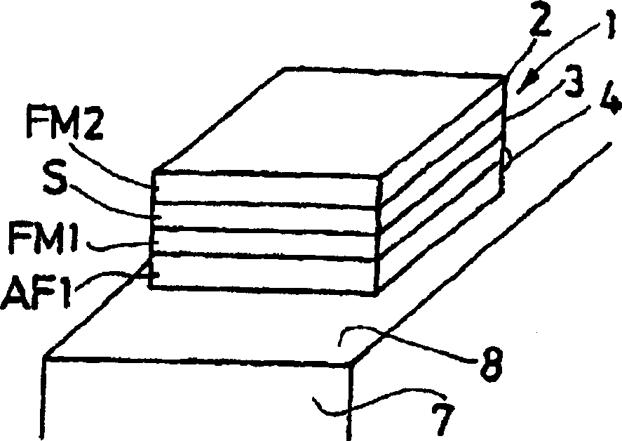
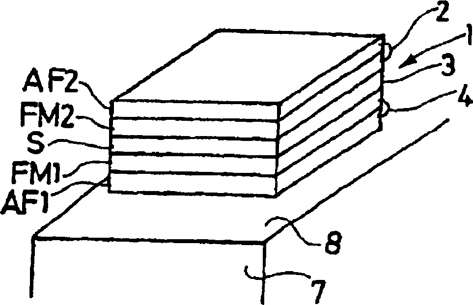
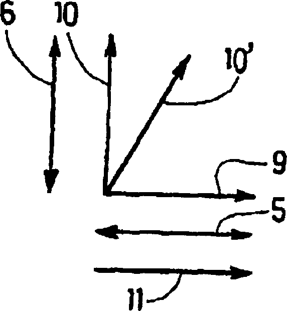
[0024] A property of particular interest here is the response obtained when a field is applied perpendicular to the magnetic axis exhibiting exchange when the ferromagnetic material FM1 and the antiferromagnetic material AF1 have a common interface. In this case, the process of magnetization reversal by nucleation and wall propagation (reversal when the field is applied along the magnetic axis exhibiting exchange) is replaced by a reversible rotation of the magnetization (when the field is perpendicular to the magnetic axis exhibiting exchange inversion when applied). Then the hysteresis characteristic is Figure 4a instead of the reversible properties. Furthermore, the signal is linear over a fairly wide field range.

[0025] Formally, the gradient of the magnetization response to the applied magnetic field is given by:

[0026] ∂ M ∂ H | H ...


PUM


Abstract

The invention relates to a magnetoresistive sensor for magnetic fields comprising a stack (1) of a reference element (2), a separating element (3) and an element (4) sensitive to a magnetic field, wherein the reference element (2) and the sensitive The element (4) has first and second magnetic anisotropy (5, 6) in first and second directions, respectively. The sensitive element (4) comprises a superposition of layers of ferromagnetic material (FM1) and of antiferromagnetic material (AF1) arranged to give a magnetic moment (10) whose component in the direction of the field to be measured is taken as The function of the measured magnetic field varies reversibly and linearly in an adjustable field range. The invention also relates to the use of such sensors.

Description

technical field [0001] The invention relates to a magnetoresistive magnetic field sensor and the use of such a sensor for measuring the strength of a magnetic field. Background technique [0002] Historically, magnetoresistive sensors have utilized changes in the resistance of a single magnetic material that are caused by changes in the magnetic field being measured. This is the principle by which an anisotropic magnetoresistive sensor operates. However, the variation in this resistance is small. Since the discovery of giant magnetoresistance (1988) and tunneling magnetoresistance at room temperature (1995), other sensor structures have been designed with resistance changes of more than 50% at room temperature. [0003] These sensors comprise a magnetic reference element, a spacer element and a stack of magnetic elements sensitive to a magnetic field, the stack being arranged so as to have a change in resistance in relation to the magnetic field to be measured. [0004] I...

Claims


Application Information

Patent Timeline
IPC IPC(8): G01R33/09
CPCB82Y25/00G01R33/093
Inventor 米歇尔·赫恩阿兰·舒尔格雷戈里·马利诺夫斯基克里斯托弗·尼科特克里斯托弗·杜雷特
Owner S.N.R.鲁尔门斯公司
Learn More