Round tubular stapler for surgical use
A binding instrument and surgical technology, applied in the field of medical devices, can solve the problems of clamping tissue, bending of the screw rod, complex assembly, etc., and achieve the effects of easy manufacturing and assembly, preventing secondary firing, and improving performance
- Summary
- Abstract
- Description
- Claims
- Application Information
AI Technical Summary
Problems solved by technology
Method used
Image
Examples
Embodiment 1
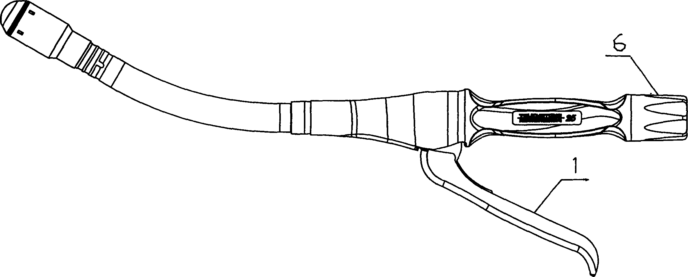
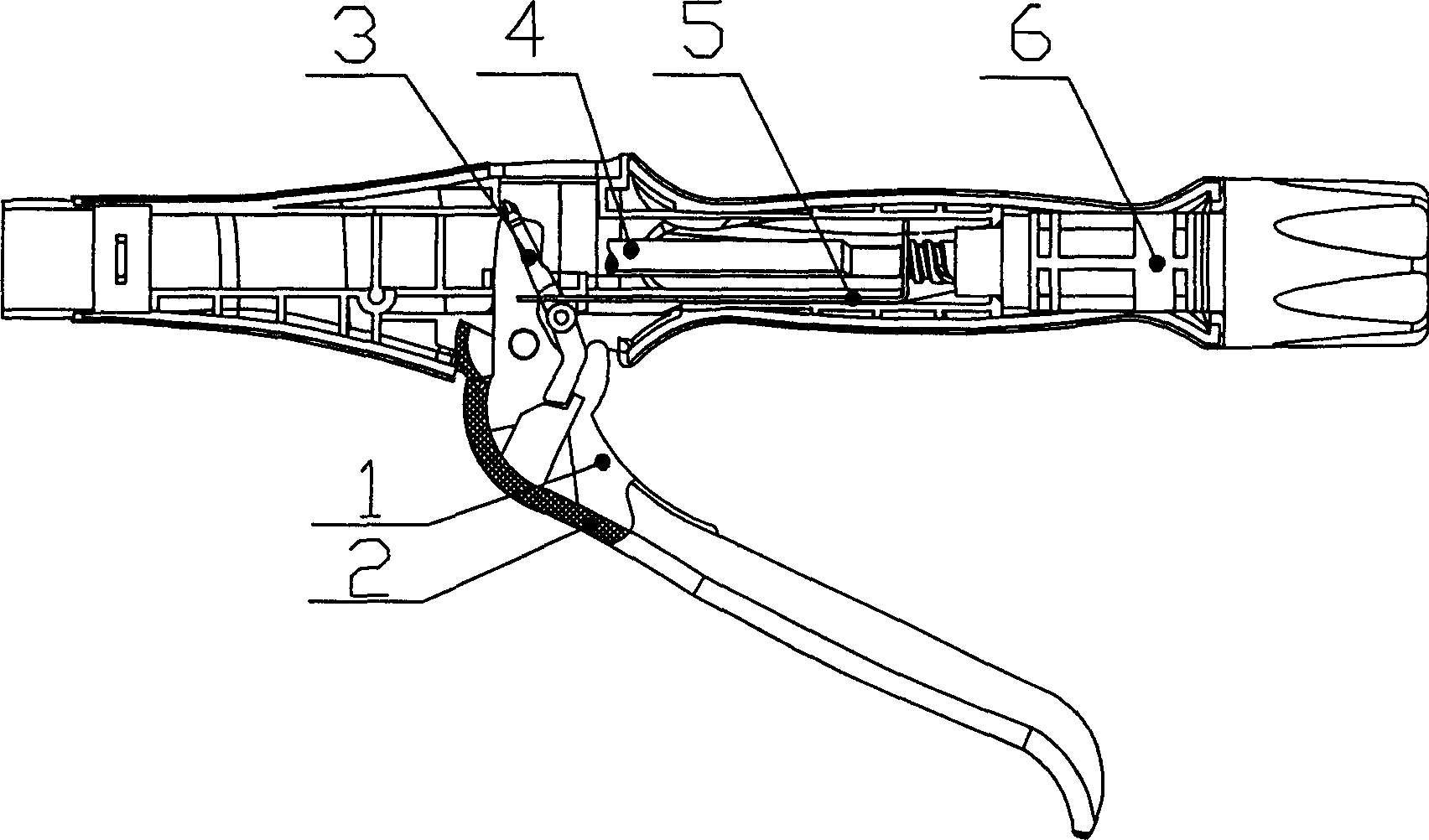
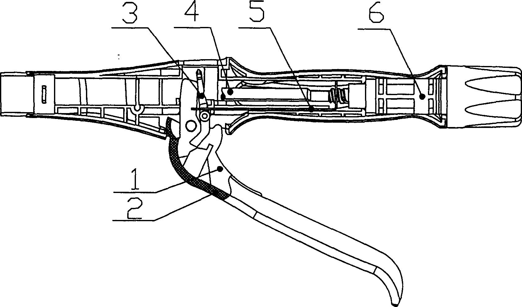
[0052] Such as Figure 1~Figure 14 As shown, the stapler of the present invention includes a stapler body, a binding head, a firing mechanism, and a transmission adjustment mechanism: the firing mechanism includes a handle 1 and a handle housing 2. The handle 1 is fixedly connected to the handle housing 2, and is pivotally connected to the stapler body The transmission adjustment mechanism includes a screw rod 4 and an adjustment knob 6, the front end of the screw rod 4 is connected with the nail anvil pull rod, and the rear end is connected with the adjustment knob 6 in a threaded manner. Similar to the prior art, a return spring is arranged between the handle 1 and the stapler body, so that the handle 1 always tends to be opened before the instrument is used.
[0053] In a technical solution of the present invention, the handle housing 2 is provided with a stopper 8, such as Figure 7 , Figure 8 Shown. In addition, a bumper 3 and a pull tab 5 are provided. One end of the bumper...
Embodiment 2
[0060] Figure 15a In the case, a hole 65 is provided in the housing 61, a hole is opened on the push rod 62, a pin 63 is placed in the hole, and the tail of the pin 63 is equipped with a spring 64; Figure 15b In the case, a boss 66 is provided inside the housing 61, a hole is opened on the push rod 62, a pin 63 is placed in the hole, and a spring 64 is installed at the tail of the pin 63; Figure 15c In the case, the housing 61 has a hole, a convex piece 67 is placed in the hole, a spring 68 is installed at the tail of the convex piece 67, and a boss 69 is arranged on the push rod 62; Figure 15d In the case, the shell 61 has a hole, and a spring sheet 70 is placed inside. A screw 71 passes through the hole to lock one end of the spring sheet 70 on the shell. At the same time, a boss 72 is provided on the push rod 62.
[0061] In this way, when the stapler is in use, the push rod moves forward, and the push rod is jammed and cannot be reset due to the cooperation of the boss, t...
Embodiment 3
[0063] Figure 16a , 16b 16c shows another embodiment of the present invention: the push rod 22 is covered with a sleeve 23, the push rod 22 is provided with a through hole, and the through hole is equipped with two pins 24a, 24b, one of the two pins There is a compression spring 25 in between. The inner wall of the housing 21 is provided with a reducing step. The smallest inner diameter of the reducing step is in an interference fit with the outer diameter of the sleeve 23, and a number of hooks are provided on one side of the reducing step 26. In the initial state, the outer ends of the pins 24a and 24b abut against the inner wall of the sleeve 23, such as Figure 16a As shown; when the instrument is fired, the push rod 22 moves forward with the sleeve 23. After the firing is completed, the sleeve 23 is caught by the hook 26, and the pins 24a and 24b are ejected under the action of the spring 25 and abut against the housing 21 protruding parts, such as Figure 16b As shown; whe...
PUM
 Abstract
Description
Claims
Application Information
 - R&D
- Intellectual Property
- Life Sciences
- Materials
- Tech Scout
- Unparalleled Data Quality
- Higher Quality Content
- 60% Fewer Hallucinations
Browse by: Latest US Patents, China's latest patents, Technical Efficacy Thesaurus, Application Domain, Technology Topic, Popular Technical Reports.
© 2025 PatSnap. All rights reserved.Legal|Privacy policy|Modern Slavery Act Transparency Statement|Sitemap|About US| Contact US: help@patsnap.com


