Liquid tank system

A technology of liquid and liquid container, applied in the field of liquid container and its manufacture

Inactive Publication Date: 2012-04-25
KC LNG TECH CO LTD ENTIRE RIGHT
View PDF3 Cites 0 Cited by
  • Summary
  • Abstract
  • Description
  • Claims
  • Application Information

AI Technical Summary

Problems solved by technology

Therefore, part of the stress is generated by shaking or the movement of the hull, and therefore, there may be stress concentration in the corner part

Method used


Image

  • Liquid tank system
  • Liquid tank system
  • Liquid tank system

Examples


Embodiment Construction

[0117] In order to further explain the technical means and effects of the present invention to achieve the intended purpose of the invention, the specific implementation, structure, characteristics and effects of the liquid storage tank system proposed according to the present invention will be described below in conjunction with the accompanying drawings and preferred embodiments. , as detailed below.

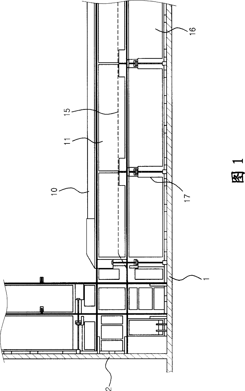
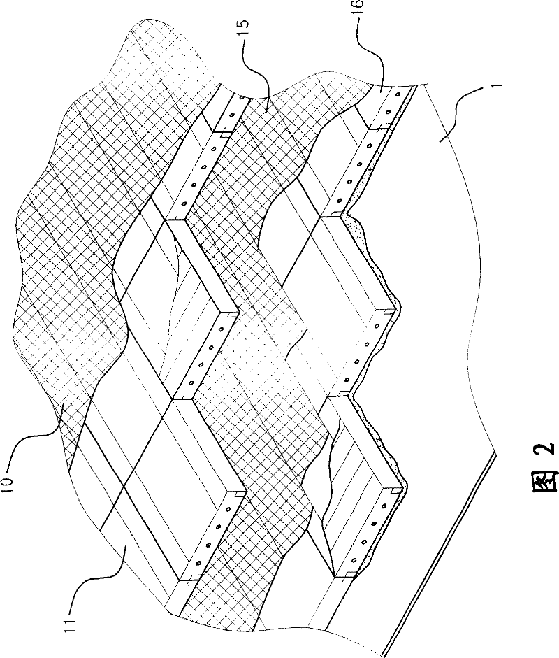
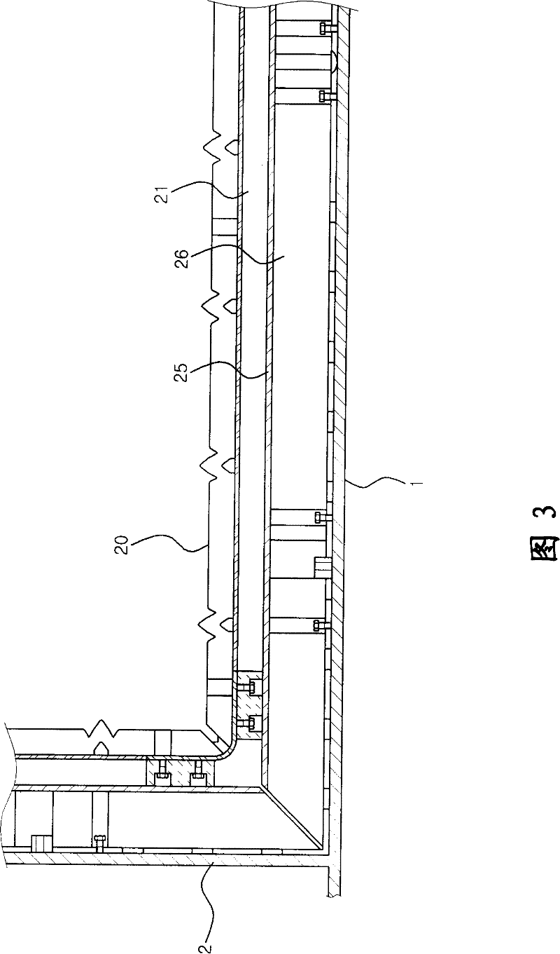
[0118] The invention relates to a liquefied natural gas storage tank for storing high-pressure and low-temperature liquefied natural gas. All the while, this LNG storage tank is constructed to be impact resistant and liquid tight at all times.

[0119] The LNG storage tank installed on a car or ship in which cargo moves is different from an underground storage tank that hardly moves because suitable countermeasures should be prepared to eliminate mechanical stress due to cargo moving inside the tank. However, the same mechanical stress relief measures used for LNG storage tan...


PUM


Abstract

Disclosed is a liquid container adapted to store liquefied natural gas (LNG). The LNG storage container include a sealing wall directly contacting liquid contained in the tank and a structural wall, which comprises an exterior wall and a interior wall and a dividing wall which last two integrated with the exterior wall by a connecting wall. The container further includes a plurality of connectors mechanically connecting the sealing wall and the structural wall and an intermediate wall structure positioned between the structural wall and the interior wall. The intermediate wall structure is configured to move relative to at least one of the sealing wall and the structural wall.

Description

technical field [0001] The invention relates to a liquid container and a manufacturing method thereof, in particular to a liquid storage tank system. Background technique [0002] Generally, liquefied natural gas (LNG) is produced by liquefying natural gas, a fossil fuel. A liquefied natural gas storage tank is classified into an underground storage tank installed or buried underground, and a mobile storage tank installed on transportation devices such as automobiles and ships, according to installation locations. [0003] The above-mentioned liquefied natural gas (LNG) is stored at low temperature and may explode when shaken. Therefore, the liquefied natural gas (LNG) storage tank should be constructed stably to maintain impact resistance and liquid tightness. A liquefied natural gas (LNG) storage tank installed on a moving car or ship is slightly different in structure from an underground storage tank that hardly moves, because a mobile LNG storage tank needs to provide ...

Claims


Application Information

Patent Timeline
Patent Type & Authority Patents(China)
IPC IPC(8): F17C1/00F17C1/02B63B25/08B63B3/68F17C3/02
CPCF17C2221/033F17C3/027F17C2260/016F17C2270/0107F17C2203/0333F17C2201/054F17C2209/232F17C2270/0171F17C2270/0173F17C2260/033F17C2205/0119F17C2209/221F17C2209/228F17C2270/0105F17C2203/0617F17C2270/0168F17C2203/0631F17C2223/033F17C2223/0161F17C2201/0166F17C2203/0358F17C2201/052B63B3/68B63B25/08
Inventor 梁永明洪性浩尹仁铢杨泳哲徐兴锡金知勋吴秉泽金映均
Owner KC LNG TECH CO LTD ENTIRE RIGHT
Why Eureka
Try Eureka