Slag-removing pot cleaning machine for metallurgy furnace

A metallurgical furnace and component technology, applied in the field of metallurgical furnace slag removal device, can solve the problems of surrounding environmental pollution, reduce the effective volume of slag pot, etc., and achieve the effects of improving work efficiency, shortening time for slag dumping, and convenient operation

Inactive Publication Date: 2006-06-14
SHANXI TAIGANG STAINLESS STEEL CO LTD
View PDF0 Cites 6 Cited by
  • Summary
  • Abstract
  • Description
  • Claims
  • Application Information

AI Technical Summary

Problems solved by technology

Some metallurgical enterprises also lay a layer of powder and dry slag on the bottom of the slag pot to prevent the slag liquid from sticking to the wall of the slag pot, which reduces the effective volume of the slag pot, and the dry slag and powder will pollute the surrounding environment during slag discharge

Method used


Image

  • Slag-removing pot cleaning machine for metallurgy furnace
  • Slag-removing pot cleaning machine for metallurgy furnace
  • Slag-removing pot cleaning machine for metallurgy furnace

Examples


Embodiment Construction

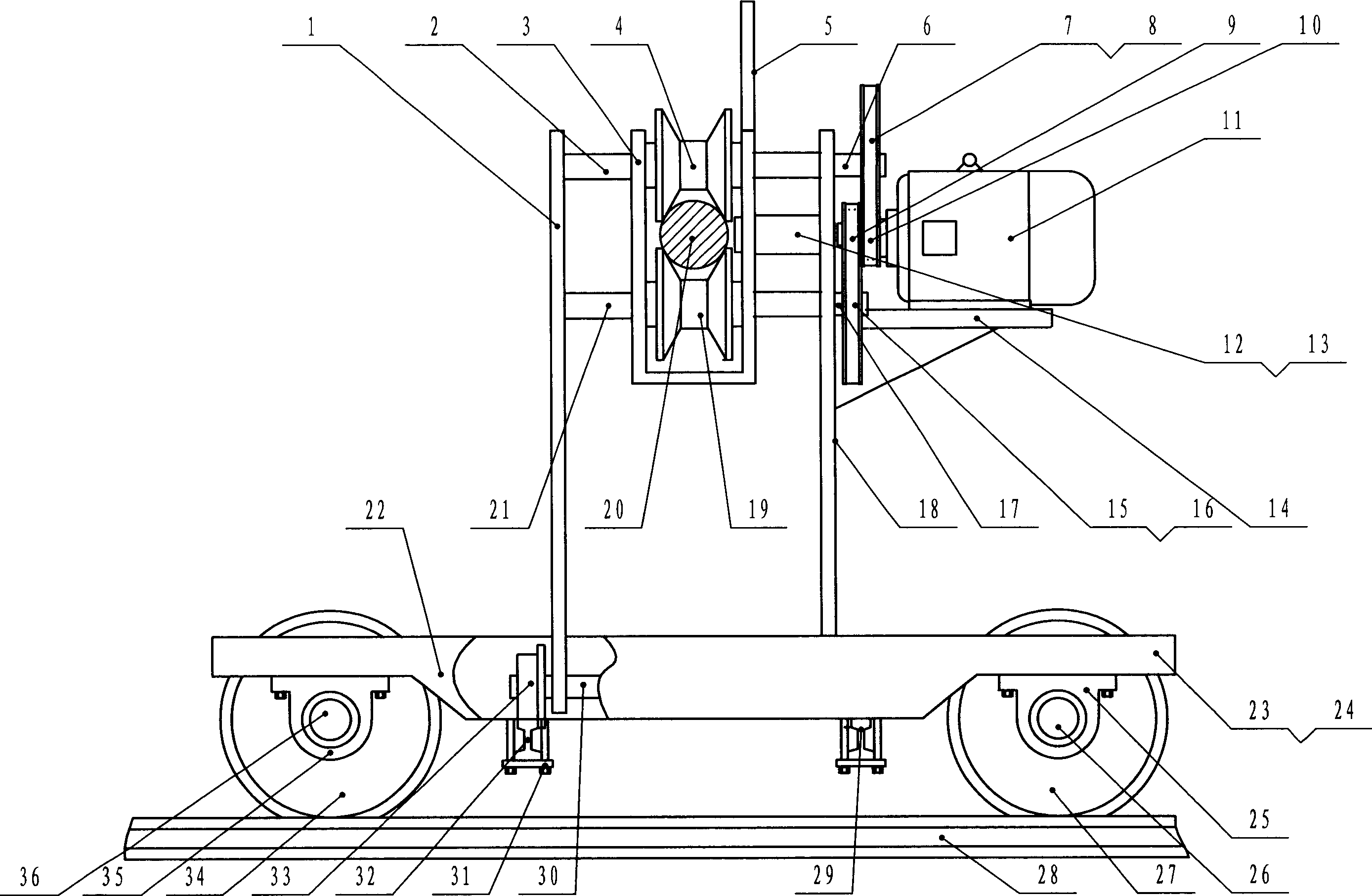
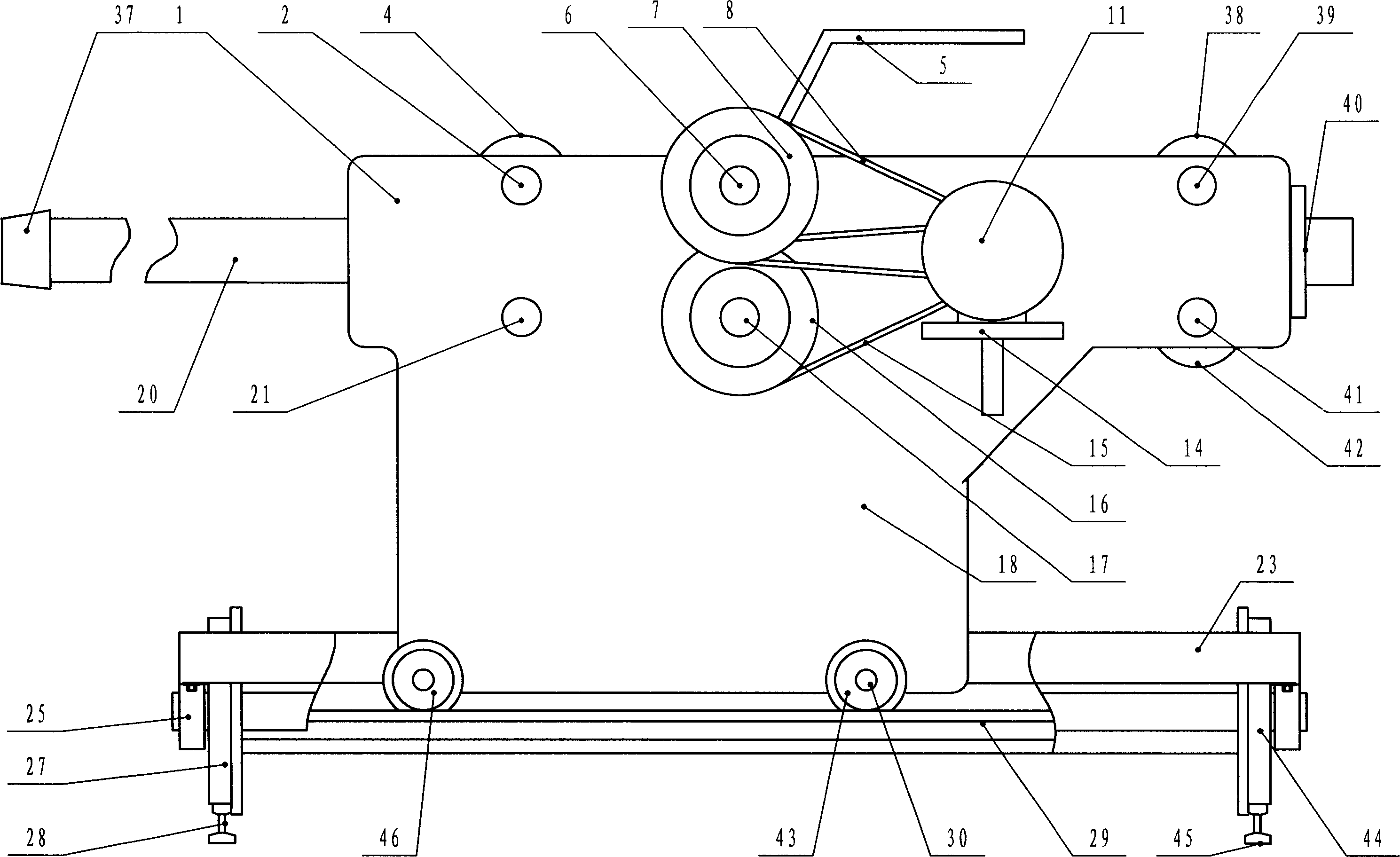
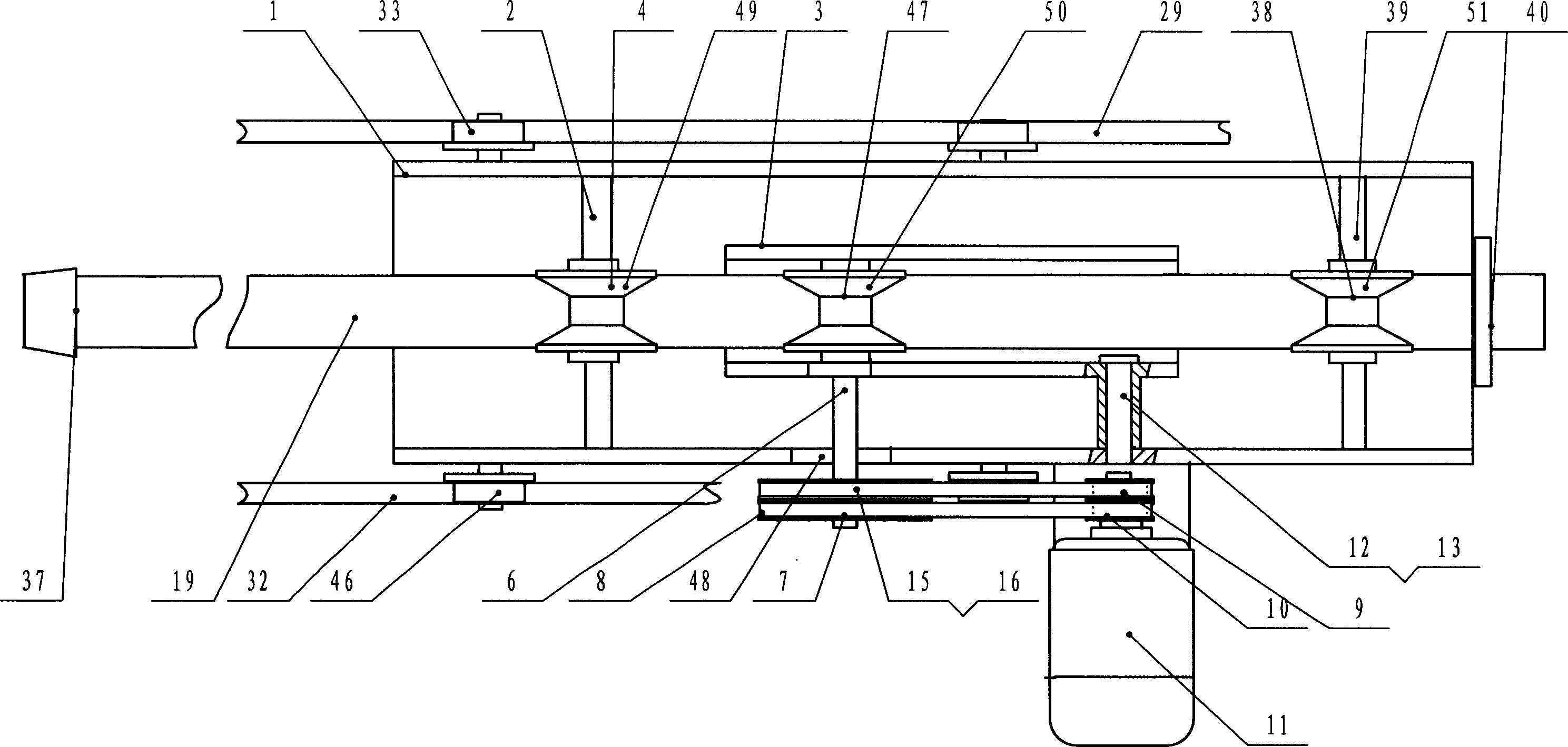
[0027] The specific implementation of the metallurgical furnace slag cleaning machine will be described in detail below in conjunction with the examples, but the specific implementation of the metallurgical furnace slag cleaning machine is not limited to the following examples.

[0028] figure 1 , figure 2 and image 3 The described metallurgical furnace slag cleaning machine includes a pounding element and a pounding element driving device, and the pounding element is installed on the pounding element driving device, and it is characterized in that: said pounding element is a pounding lever 20, and the Said pounding pot element driving device is a potting car, and the potting car has a bottom car 22 that moves on the ground rail and a main car 1 that moves on the bottom car 22, and the bottom car 22 has a frame-shaped vehicle frame 23. Shaped vehicle frame 23 is equipped with four iron wheels, and the width of two relative iron wheels matches with two rails on the ground, ...


PUM


Abstract

The invention relates to furnace deslagging boiler cleaning machine. It includes pounding boiler component and its drive unit. Its features are that the former is pounding boiler bar; the latter is pounding boiler carriage. The pounding boiler carriage has bottom carriage and main carriage. The frame of the former is set two rails. The erect frame of the latter is set on the former. The front and bake ends of the erect frame upper are set two trough running rollers. The pounding boiler bar is set among them. One of the running rollers is set at the erect frame. The upper through running roller is blocked at pounding boiler bar. And its two running roller shaft is fixed on driven driving wheel in stationary state. The operation of the invention is convenient and safe, can shorten deslagging time, and increase work efficiency.

Description

technical field [0001] The invention relates to a device for removing slag and cleaning pots of metallurgical furnaces. Background technique [0002] Blast furnace, electric furnace, converter metallurgical slag, in the process of using the slag pot to discharge the slag liquid, often a part of the slag accumulates on the bottom of the slag furnace, because the temperature of the slag is very high, it is difficult to remove, this part of the slag liquid will stick to the bottom of the slag furnace after cooling. The bottom of the slag pot, so that the slag accumulates thicker and thicker at the bottom of the slag pot, and the volume of the slag pot decreases, which seriously affects the normal use of the slag pot. Whether the slag pot can be discharged on time directly affects the normal operation of the blast furnace, electric furnace, and converter, and whether the slag can be discharged normally is a major link affecting the discharge of the slag pot. Now there is no ded...

Claims


Application Information

Patent Timeline
Patent Type & Authority Applications(China)
IPC IPC(8): F27D3/15
Inventor 王桂萍周艮双
Owner SHANXI TAIGANG STAINLESS STEEL CO LTD
Why Eureka
Try Eureka