Backlight module structure

A technology of backlight module and light-emitting surface, applied in optics, nonlinear optics, instruments, etc., can solve the problems of inability to effectively use the limited space of products, weaken the light intensity of light-emitting diodes, increase production costs, etc.

Active Publication Date: 2006-06-14
AU OPTRONICS CORP
View PDF0 Cites 6 Cited by
  • Summary
  • Abstract
  • Description
  • Claims
  • Application Information

AI Technical Summary

Problems solved by technology

Although the distance between the light emitting diodes 10 and 12 and the active area can be enlarged, the corner dark band area 30 can be reduced, but this method will weaken the light intensity of the light emitting diodes 10 and 12 on the active area, thus requiring a larger po...

Method used


Image

  • Backlight module structure
  • Backlight module structure
  • Backlight module structure

Examples


Embodiment Construction

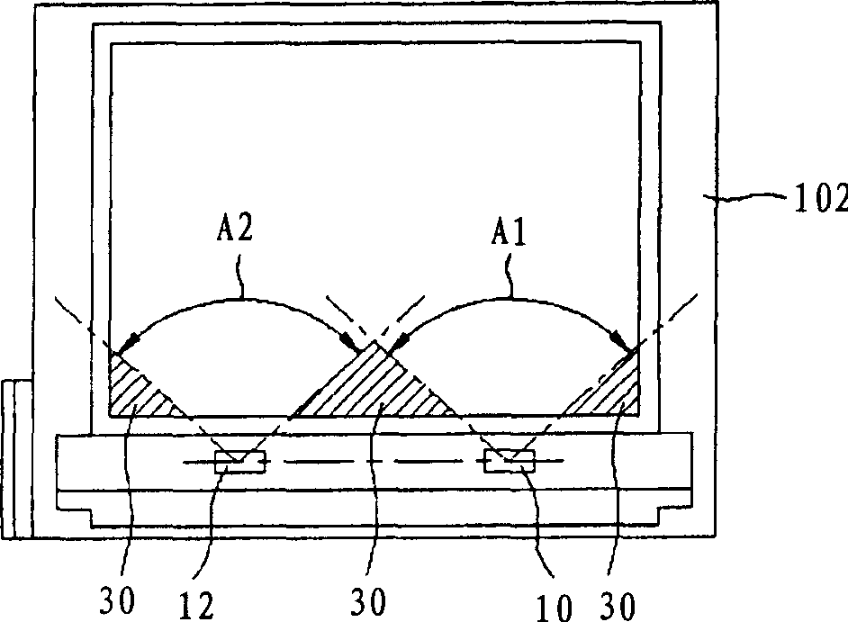
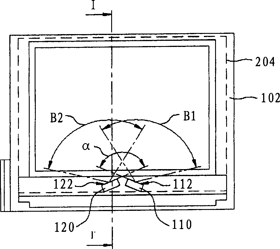
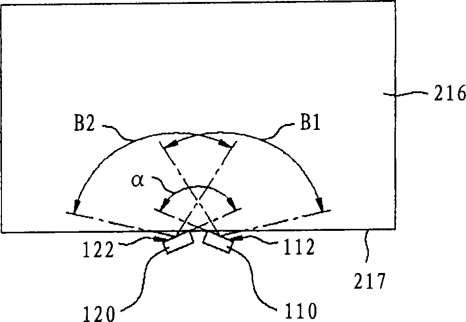
[0032] In the backlight module structure of the present invention, two adjacent light-emitting diodes are adjacently arranged on the light guide plate, and the light-emitting surface of each light-emitting diode is inclined outward at a preset angle, wherein the two light-emitting surfaces of the two light-emitting diodes extend out The outside angle is between about 90 degrees and 180 degrees.

[0033] Please refer to Figure 2A with Figure 2B , Figure 2A is a schematic diagram illustrating a liquid crystal display according to a preferred embodiment of the present invention; Figure 2B It is a schematic diagram illustrating the structure of an LED backlight module according to a preferred embodiment of the present invention.

[0034] Such as Figure 2A As shown, the liquid crystal display of the present invention includes a rectangular frame body 102 with four connected sides, a liquid crystal panel 204 and a backlight module structure (not shown), wherein the backligh...


PUM


Abstract

The invention discloses a backlight module that could reduce the dark band area. Two proximate LED in the backlight module structure are set next to light guiding board. Each emitting side is inclined outward a preset angle. The outside included angle between the two emitting sides is between 90 degree and 180 degree.

Description

technical field [0001] The invention relates to a backlight module structure, in particular to a light-emitting diode (LED) backlight module structure capable of reducing dark zone areas in corners. Background technique [0002] The backlight module is one of the basic components of a liquid crystal display (Liquid Crystal Display; LCD). Since the liquid crystal itself does not emit light, the required light source needs to be provided through the backlight module. The operating principle of the backlight module is to guide the light from the backlight through the light guide plate to form a flat light source to ensure the uniformity of brightness. Commonly used backlight sources for backlight modules include cold cathode fluorescent lamps and light emitting diodes, for example. Although cold-cathode fluorescent lamps are currently the mainstream, the demand for light-emitting diodes is increasing day by day. Compared with cold-cathode fluorescent lamps, light-emitting di...

Claims


Application Information

Patent Timeline
IPC IPC(8): G02F1/1335
Inventor 郭汉斌
Owner AU OPTRONICS CORP
Why Eureka
Try Eureka