
Data communication system, communication device, and communication program thereof

A data communication system and data packet technology, applied in the field of communication, can solve problems such as saving wireless resources, communication itself cannot communicate, and data volume reduction

Inactive Publication Date: 2006-06-28
NEC CORP
View PDF0 Cites 4 Cited by
  • Summary
  • Abstract
  • Description
  • Claims
  • Application Information

AI Technical Summary

Problems solved by technology

[0022] At this time, in area A, network N communicates with services x1 and x2 provided by communication operator X, but since network N moves to area B, service x2 becomes unavailable, and the amount of data that can be transmitted decreases
Furthermore, since the network N moves to the area C, it becomes impossible to receive the service of the communication operator X, and the communication itself becomes a state where communication cannot be performed.
Here, the network N is also included in the service provided by the communication carrier Y, but in the prior art, there is no technology for combining the services of the different communication carrier X and the service of the communication carrier Y, and the moving destination cannot be accepted. The service of communication operator Y
[0023] In addition, the existing technology represented by the above-mentioned IETF Internet Draft (draft-ernst-nemo-terminology-01.txt) does not have a component that saves wireless resources irrelevant to the network operator

Method used


Image

  • Data communication system, communication device, and communication program thereof
  • Data communication system, communication device, and communication program thereof
  • Data communication system, communication device, and communication program thereof

Examples


Embodiment 1

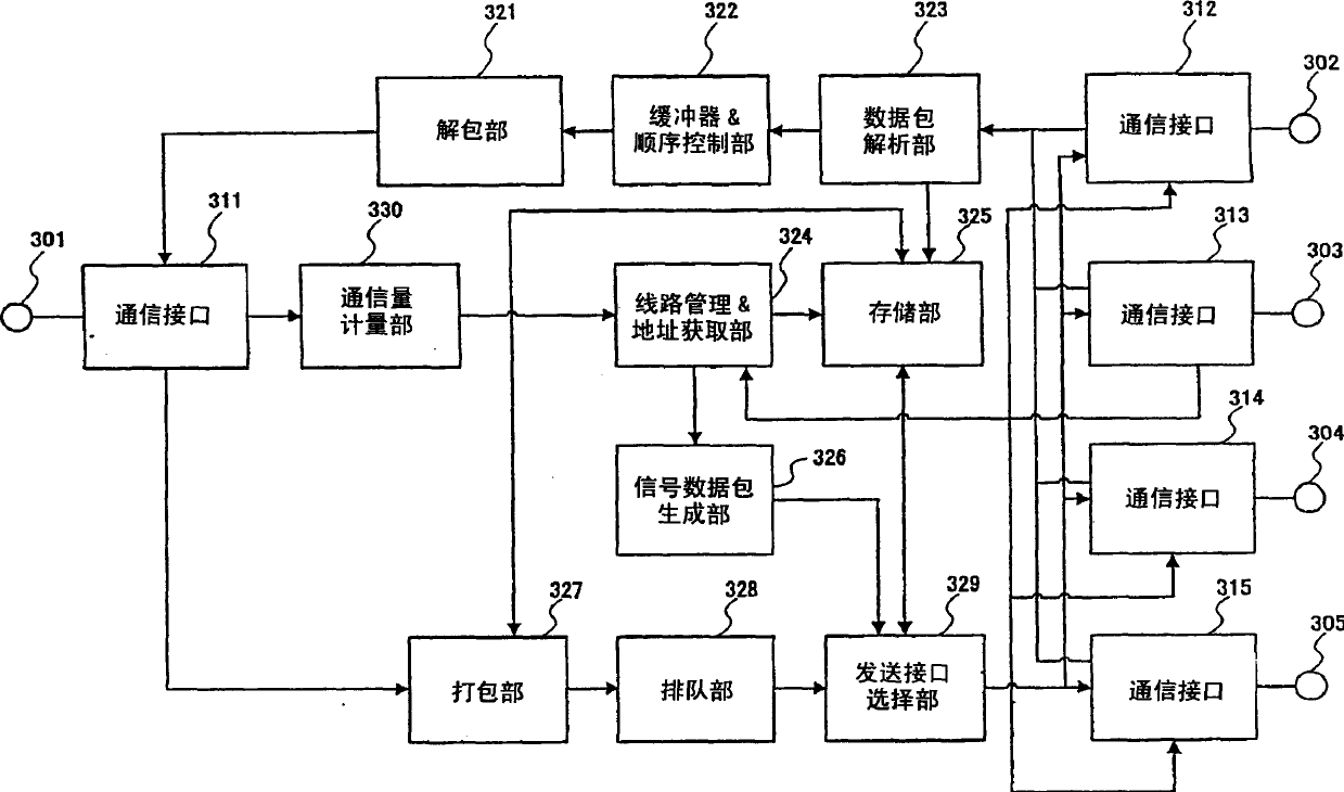
[0575] In addition, in the description of Embodiment 1 below, we illustrate the overall operation policy information 2310, each communication interface operation policy information 2320, statistical information 2400, and communication interface quality information 2500 using FIGS. 23, 24, and 25. In addition, we describe the specific action flow with reference to the action operation sequence diagram in FIG. 26 .

[0576] 27 is a graph plotting actual performance values ​​2600 and target minimum values ​​2610 for communication rate per unit of time as the mobile network 104 moves from point A to point B. FIG.

[0577] As shown in the figure, the transmission interface selection unit 329 starts the communication interface selection process because the actual performance value 2600 of the communication rate is lower than the target minimum value 2610 .

[0578] Since the downlink communication rate to be filled is 30 kbps, the transmission interface selection unit 329 retrieves ...

Embodiment 2

[0584] Next, we describe Example 2 which shows the specific operation of the above-mentioned embodiment. As opposed to making the target minimum value of the downlink communication rate between point A and point B in the above-mentioned first embodiment, in this second embodiment, the method of allocating the target minimum value of the communication rate with an additional weight according to the occupancy rate will be described. example.

[0585] In addition, in the description of the second embodiment below, we use the overall operation strategy information 2310 shown in FIG. 28 and the statistical information 2400 and communication interface quality information 2500 shown in FIGS. 23 and 24 for illustration. In addition, we describe the specific action flow with reference to the action operation sequence diagram in FIG. 26 .

[0586] 29 is a graph plotting actual performance values ​​2650 and target minimum values ​​2660 for communication rate per unit of time as mobile n...

Embodiment 3

[0606] Next, we describe Example 3 which shows the specific operation of the above-mentioned embodiment.

[0607] In contrast to the change in the downlink communication rate used as the trigger to start the communication interface selection process in the first and second embodiments, the change in the communication fee is used as the trigger to start the communication interface selection process in this embodiment.

[0608] In addition, in the description of the third embodiment below, we use the overall operation policy information 2310 shown in FIG. 23 , the statistical information 2400 shown in FIG. 24 , and the communication interface quality information 2500 shown in FIG. 25 for description. In addition, we describe the specific action flow with reference to the action operation sequence diagram in FIG. 26 .

[0609] FIG. 30 is a graph plotting an actual achievement value 2700 and a target upper limit value 2710 of the communication fee per unit time when the mobile net...


PUM


Abstract

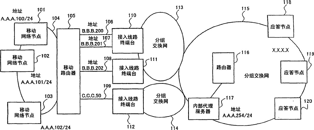
The present invention provides a technology for data communication that can flexibly secure a frequency band for the amount of traffic that occurs, and efficiently utilize access lines or wireless resources. The mobile router maintains a plurality of narrowband communication paths with an internal proxy server using a plurality of communication components, and constructs a broadband communication path by logically using the plurality of narrowband communication paths as one communication path. Therefore, it is possible to flexibly secure a frequency band according to the amount of traffic occurring in the mobile network. In this case, the internal proxy server can effectively use the access line by referring to the routing information to determine the destination. In addition, by dynamically connecting new lines and disconnecting existing lines according to user requests, it is possible to save user-led wireless resources.

Description

technical field [0001] The present invention relates to the communication technology using mobile network, in particular, relates to the technology of combining communication components providing the same type and different types of services in the mobile packet communication network to form a logical line and ensure broadband access line. Background technique [0002] It is our intention to more fully describe the state of the art at the present time concerning the present invention, which are incorporated herein by reference to the patents, patent applications, patent publications, scientific papers, etc. cited or specified in this patent application, which are incorporated in the entirety of the present invention. in description. [0003] As technologies related to network mobility, technologies of IETF NEMO WG (Internet Engineering Task Force Network Mobility Working Group (Internet Engineering Task Force Network Mobility Working Group)) are mentioned. Referring to IETF...

Claims


Application Information

Patent Timeline
Patent Type & Authority Applications(China)
IPC IPC(8): H04L45/85H04L47/41H04L47/43H04W4/00H04W8/04H04W28/00H04W40/22H04W40/34H04W48/18H04W76/02H04W80/04H04W84/00H04W88/10
CPCH04L41/048H04W8/04H04W80/04H04W84/005H04W8/10H04W8/06
Inventor 中田恒夫小野真裕百名盛久冈上和广
Owner NEC CORP
Learn More