
Trochoid oil pump

A kind of cycloid and trochoid technology, applied in the direction of pumps, pump components, rotary piston type/swing piston type pump components, etc., can solve the problem of difficult to prevent the pressure rise of the shrinking chamber, shrinking the gap to a small extent, and difficult to shrink the chamber. Connectivity and other issues to prevent erosion, reduce pulsation, and improve durability

Inactive Publication Date: 2006-07-05
YAMADA SEISAKUSHO KK
View PDF1 Cites 7 Cited by
  • Summary
  • Abstract
  • Description
  • Claims
  • Application Information

AI Technical Summary

Problems solved by technology

Through such a gap, a part of the liquid in the contraction chamber is discharged to the adjacent contraction chamber and discharge chamber as the volume of the contraction chamber decreases, and the size of the gap is not one side in the direction of rotation relative to the volume reduction of the contraction chamber. The upper expansion side is maintained, but the gap is quickly reduced to a small size, making it difficult to fully communicate with the adjacent contraction chamber
[0006] Therefore, the amount of liquid released to the adjacent constriction chamber by contraction is small, and it is difficult to prevent excessive pressure rise in the constriction chamber, and it is also difficult to avoid noise caused by cavitation.

Method used


Image

  • Trochoid oil pump
  • Trochoid oil pump
  • Trochoid oil pump

Examples


Embodiment Construction

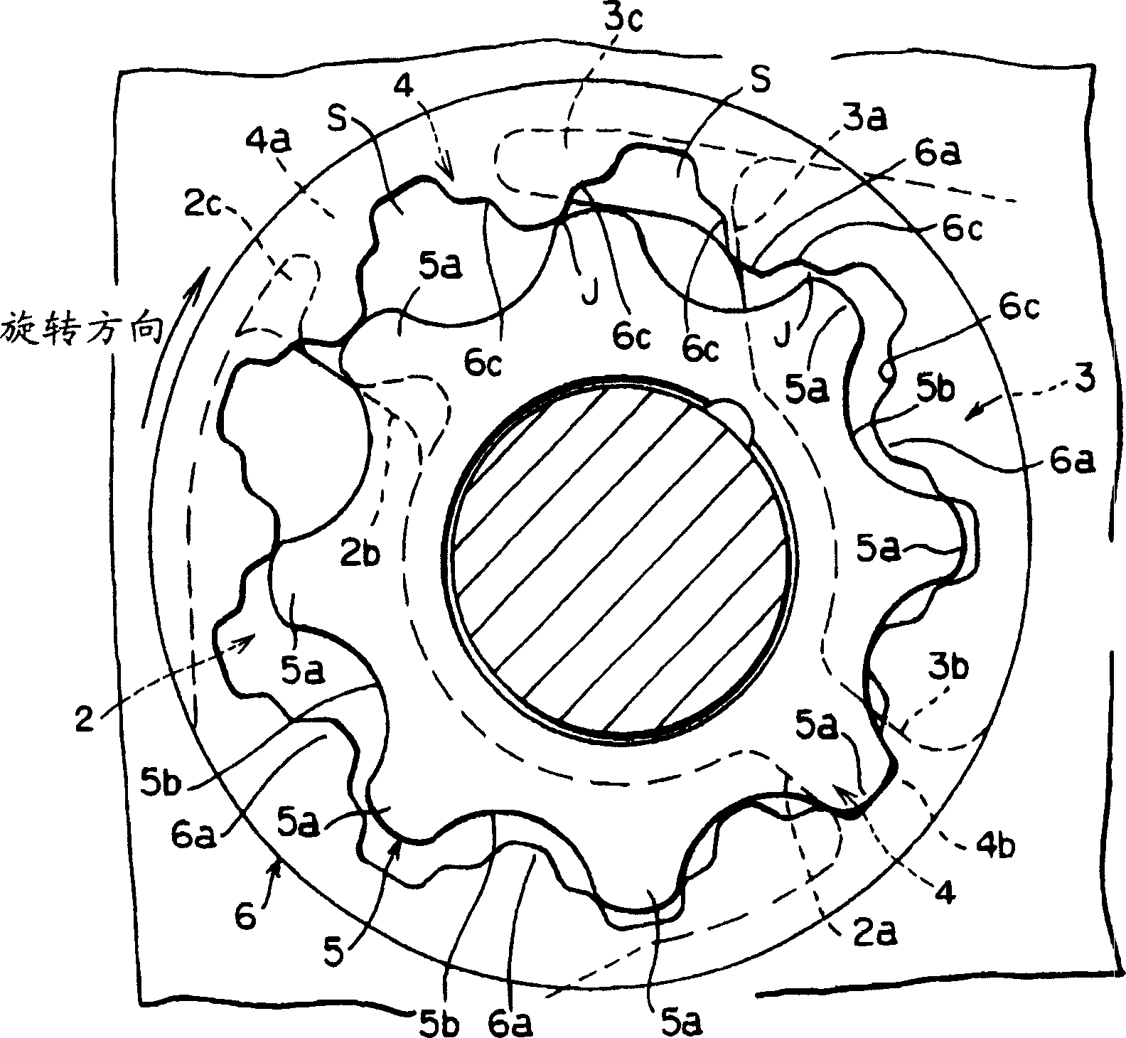
[0022] Hereinafter, the best mode for carrying out the present invention will be described based on the drawings. In the trochoid pump of the present invention, as shown in FIG. 1(A), a trochoid tooth-shaped inner rotor 5 and an outer rotor 6 are housed in a rotor chamber 1 formed in a pump casing. In the rotor chamber 1, as shown in FIG. 1(A), a suction port 2 and a discharge port 3 are formed substantially on the outer periphery along the circumferential direction thereof. Specifically, as shown in Figure 1(A), Figure 4 As shown in (A) etc., the suction port 2 and the discharge port 3 have left-right asymmetrical shapes, and the area area of ​​the suction port 2 is formed larger than that of the discharge port 3 .

[0023] At the suction port 2, as shown in FIG. 1(A), the inter-tooth space S formed by the rotation of the inner rotor 5 and the outer rotor 6 moves, and the end portion of the area first reaching the above-mentioned suction port 2 becomes a suction port. The ...


PUM


Abstract

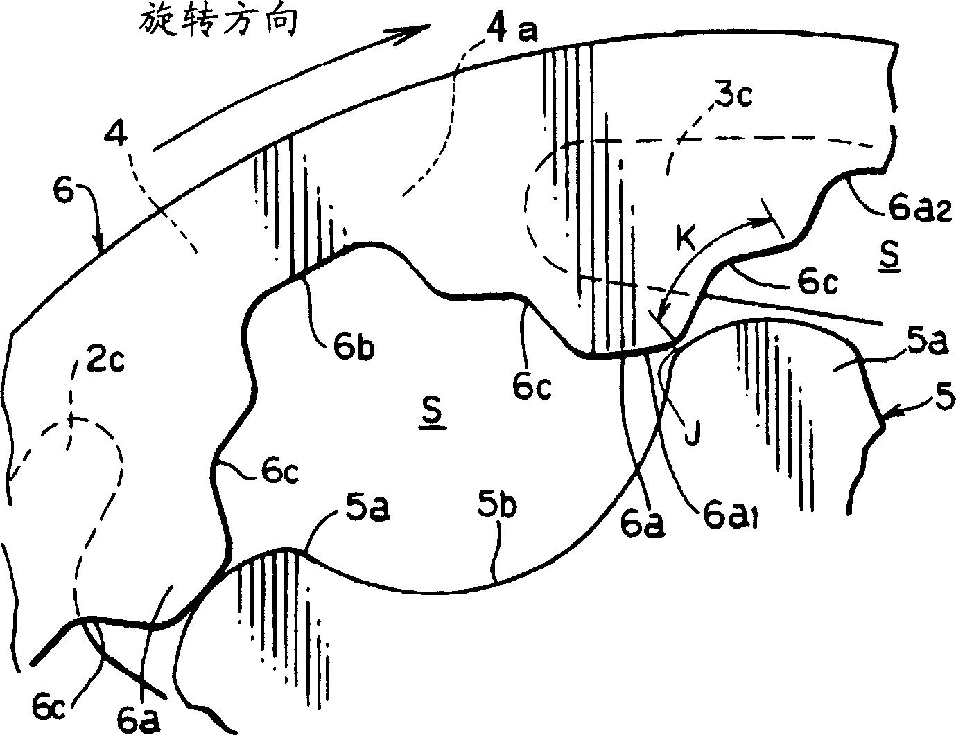
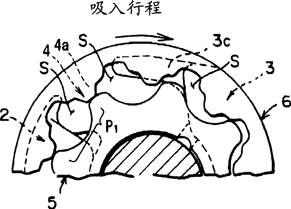
To provide a trochoid type oil pump materializing improvement of durability and reduction of delivery pulsation and noise with a very simple structure. In this oil pump, a space S between teeth composed by an inner rotor 5 including trochoid teeth or roughly trochoid shape teeth starts compression stroke P3at four section of partition part 4 between an intake port 2 and a delivery port 3, a communication gap J with preceding adjoining space S between teeth in delivery stroke P4is constructed in the space S between the teeth. The communication gap J gradually expands from start of compression stroke P3to delivery stroke P4.

Description

technical field [0001] The present invention relates to a trochoidal oil pump capable of improving durability, reducing discharge pulsation and noise, and achieving the above objects with an extremely simple structure. Background technique [0002] Japanese Patent Laid-Open No. 5-215079 discloses the following scheme: the tooth surface on the rear side in the rotation direction of each tooth of the external tooth gear of the internal gear pump, or the tooth surface on the front side in the rotation direction of each tooth of the internal tooth gear A portion of the tooth surface is recessed over the entire tooth width to form a gap between the facing tooth surface and the adjacent constriction chamber and between the constriction chamber and the discharge chamber. [0003] [Patent Document 1] Japanese Patent Application Laid-Open No. 5-215079 [0004] The technical content disclosed in Patent Document 1 is to form a concave portion on a part of the tooth surface of an exter...

Claims


Application Information

Patent Timeline
Patent Type & Authority Applications(China)
IPC IPC(8): F04C2/10
CPCF04C2/084F04C2/102F04C15/0007
Inventor 远坂和郎笠原昌广小野靖典藤木谦一甲斐圭一千贺义明金子敦史
Owner YAMADA SEISAKUSHO KK
Learn More