LCD faceplate

A liquid crystal display panel and display area technology, applied in the direction of static indicators, etc., can solve the problems of incomplete curing of the frame glue, poor display characteristics of the liquid crystal panel, etc., and achieve the effect of improving the utilization rate

Inactive Publication Date: 2006-07-05
INNOCOM TECH SHENZHEN +1
View PDF0 Cites 12 Cited by
  • Summary
  • Abstract
  • Description
  • Claims
  • Application Information

AI Technical Summary

Problems solved by technology

[0008] In order to overcome the defect that the typesetting design of the peripheral structure of the liquid crystal display panel in the prior art tends to cause the sealant to not completely cure during the manufacturing process, resulting in poor display characteristics of the liquid crystal panel, the present invention provides a liquid crystal display panel that can fully cure the sealant

Method used


Image

  • LCD faceplate
  • LCD faceplate
  • LCD faceplate

Examples


Embodiment Construction

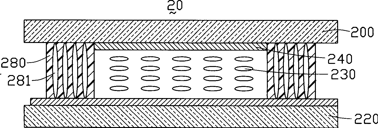
[0014] Please refer to figure 2 , is a schematic cross-sectional view of the first embodiment of the liquid crystal display panel of the present invention. The liquid crystal display panel 20 includes a first substrate 200 , a second substrate 220 , a liquid crystal layer 230 and a sealant 280 . Wherein, the first substrate 200 and the second substrate 220 are arranged opposite to each other, the liquid crystal layer 230 is sandwiched therebetween, and the sealant 280 is arranged between the first substrate 200 and the second substrate 220, and the first substrate 200 and the second substrate are closely bonded. The second substrate 220 also frames the liquid crystal molecules between the first substrate 200 and the second substrate 220 .

[0015] A black matrix 240 is disposed on the surface of the first substrate 200 facing the second substrate 220 , and the outside of the black matrix 240 extends to the edge of the display area (the area where the liquid crystal 230 is loc...


PUM


Abstract

The invention reveals a liquid crystal display panel, comprising: a first substrate whose one surface is provided with a black matrix whose outside extends to the edge of a display region; a second substrate; nontransparent frame glue, arranged around the black matrix to connect with the first and second substrates. The invention need not occupy the glass substrate to coat the frame glue, thus raising the utilization ratio of the glass substrate. In addition, the frame glue is arranged outside the black matrix, thus able to assure it can completely cure in the manufacturing process.

Description

【Technical field】 [0001] The present invention relates to a liquid crystal display panel, in particular to a structure around the liquid crystal display panel made by a One Drop Fill (ODF) method. 【Background technique】 [0002] The liquid crystal display panel is the main part of the liquid crystal display device. It mainly includes a first substrate, a second substrate, and a liquid crystal layer sandwiched between the two substrates. The first substrate and the second substrate are tightly connected by a frame glue. fit. Liquid crystal injection methods can generally be divided into two types: vacuum suction type and drop injection type. [0003] The process of vacuum inhalation of liquid crystals includes the following steps: first, two glass substrates are combined and an opening is left, and then the substrates are placed in a vacuum sealed box; then the panel is sucked in liquid crystals from the opening by using the capillary principle and pressure difference; final...

Claims


Application Information

Patent Timeline
Patent Type & Authority Applications(China)
IPC IPC(8): G02F1/133
Inventor 吴佳怡萧坤星
Owner INNOCOM TECH SHENZHEN
Why Eureka
Try Eureka