
Thermoswitch

A thermal switch and moving contact technology, applied to thermal switch components, etc., can solve the problem of inability to obtain on-resistance, etc., and achieve the effect of small on-resistance and high reliability

Inactive Publication Date: 2006-07-05
ALPS ALPINE CO LTD
View PDF1 Cites 2 Cited by
  • Summary
  • Abstract
  • Description
  • Claims
  • Application Information

AI Technical Summary

Problems solved by technology

[0011] But, the movable contact 56 is arranged on the free end of the bimetal 55 supported by the cantilever, as Figure 8 Shown in (a), (b), in the activation process, the front end of the bimetal 55 will Figure 8 (a) state to Figure 8 The state of (b) is deformed, and the side of the movable contact 56 is tilted in the front and rear directions on the fixed contact 53, so that the contact point with the fixed contact 53 moves within the range of L1. At this time, the activation of the contact surface The area (P2 point) is different from the contact position (P1 point) at room temperature, and the desired on-resistance may not be obtained

Method used


Image

  • Thermoswitch
  • Thermoswitch
  • Thermoswitch

Examples


Embodiment Construction

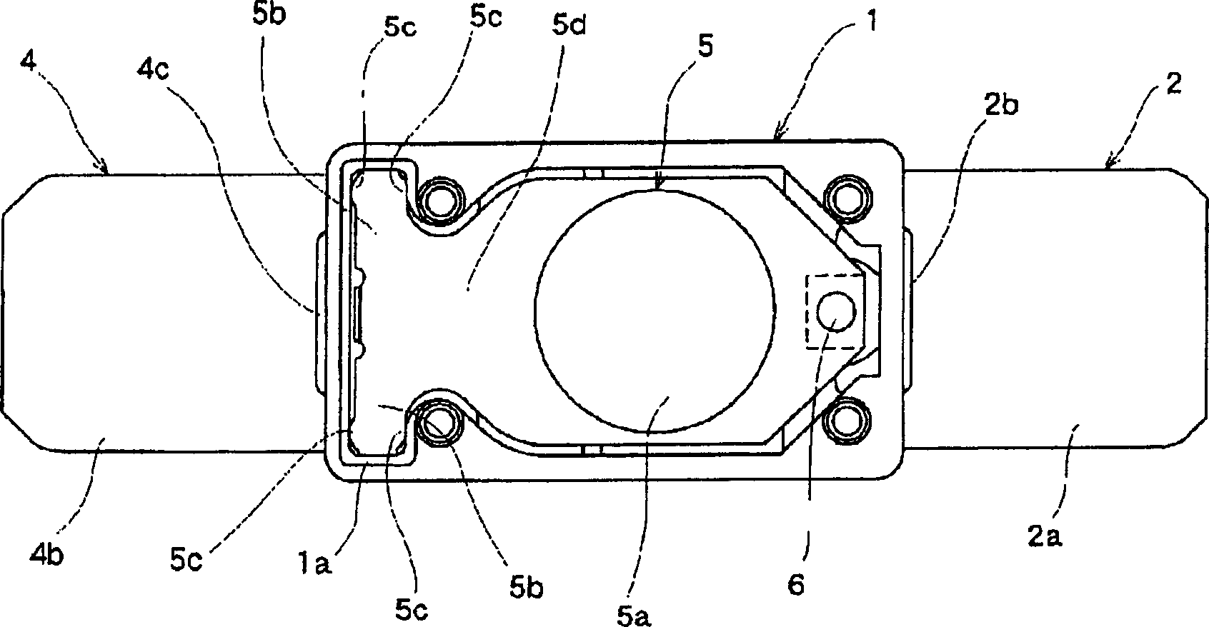
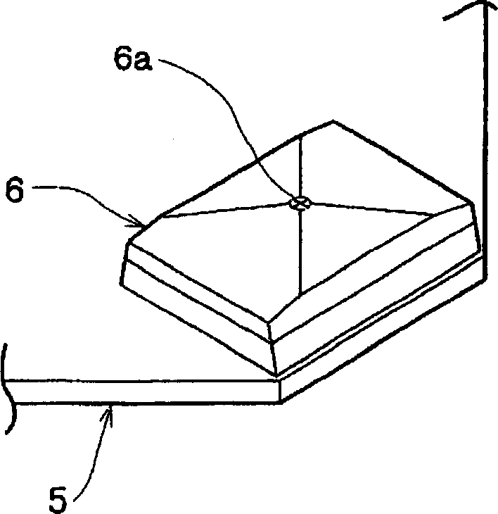
[0032] the following, Figure 1 to Figure 6 Examples of the present invention are shown. figure 1 It is a top view of the state of removing the cover of the thermal switch of the present invention; figure 2 is a sectional view of the thermal switch; image 3 is a perspective view showing the main part of the movable contact fixed to one end side of the bimetal; Figure 4 It is a perspective view of main parts showing a modified example of a movable contact fixed to one end side of a bimetal; Figure 5 is a cross-sectional view of the thermal switch showing the state before the bimetal is about to flip; Figure 6 It is an explanatory diagram showing the contact state of the movable contact and the fixed contact, (a) is a normal time, and (b) is an explanatory diagram immediately before turning over.

[0033] In the figure, the housing 1 is formed of an insulating material such as synthetic resin into a box shape with an open top. On the inner bottom of the housing 1 , te...


PUM


Abstract

To provide a thermal switch capable of reducing conduction resistance and having a high reliability. The thermal switch has a housing 1, a fixed contact 3 arranged at the inner bottom of the housing, a bimetal piece 5 which has a reversing part 5a capable of reversing according to temperatures and in which a movable contact 6 for contacting and separating from the fixed contact 3 is fixed at one end side, and a fixed terminal 4 to which the other end side of the bimetal piece 5 is fixed in cantilever form by being overlapped and which is arranged at the inner bottom of the housing 1. Projected parts 6a, 6b are provided at the contact face opposed to the movable contact 6 or the fixed contact 3, and when the movable contact 6 inclines at the swinging movement of the bimetal piece 5 immediately before reversing, the movable contact 6 is made to incline with the vicinity of the projected parts 6a, 6b as a fulcrum.

Description

[0001] technology area [0002] The invention relates to a thermosensitive switch, in particular to a switch structure which utilizes the thermal effect of a bimetal sheet to realize the flipping of a movable contact so as to open and close an electrical contact. Background technique [0003] A thermal switch (switch) is provided with a thermally sensitive element (bimetallic strip) that is bonded together with a plurality of metals with different thermal expansion coefficients as a movable contact part, and is configured together with the movable contact part. The fixed contact of the normally closed contact type circuit is connected to the circuit of the electrical equipment to protect the electrical equipment. [0004] That is to say, when the thermal switch connected to the electric machine circuit is too large or the ambient temperature is abnormally high, the structure of the switch contact opening can be formed through the bending and turning of the bimetallic strip, so...

Claims


Application Information

Patent Timeline
Patent Type & Authority Applications(China)
IPC IPC(8): H01H37/54
Inventor 泷川真喜人增田英树
Owner ALPS ALPINE CO LTD
Learn More