Check patentability & draft patents in minutes with Patsnap Eureka AI!

Circular polarized array antenna

A technology for array antennas and polarized antennas, applied to antennas, antenna unit combinations with different polarization directions, electrical components, etc., can solve the problems of complex manufacturing procedures of antenna components, achieve good signal receiving ability, easy manufacturing, and low cost Effect

Inactive Publication Date: 2010-08-18
TATUNG COMPANY +1
View PDF1 Cites 0 Cited by
  • Summary
  • Abstract
  • Description
  • Claims
  • Application Information

AI Technical Summary

Problems solved by technology

However, there is still room for improvement in the performance of conventional circularly polarized array antennas, and the manufacturing procedures of conventional antenna elements 1-1 to 1-7 are also complicated

Method used


Image

  • Circular polarized array antenna
  • Circular polarized array antenna
  • Circular polarized array antenna

Examples


Embodiment Construction

[0012] In order to better understand the technical content of the present invention, a preferred specific embodiment is given as follows.

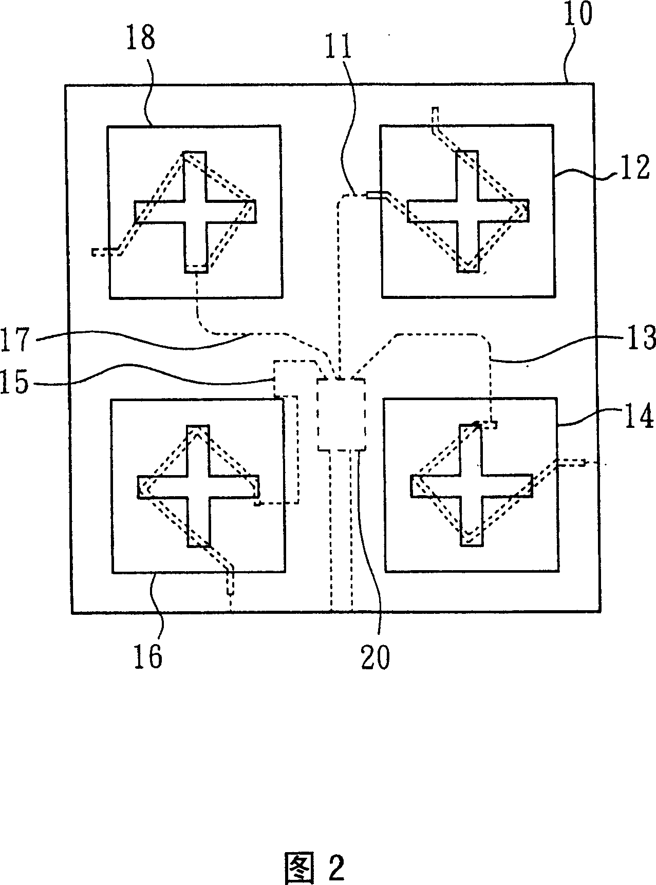
[0013] As shown in Figure 2, the circularly polarized antenna 10 of the present invention includes the following elements: antenna units 12, 14, 16, and 18, the structure of each antenna unit is all the same, and the antenna unit 12 is used as an example for illustration, but not This is the limit. As shown in Figure 3, the antenna unit 12 further includes: a protective film 22, a microstrip antenna (including a support layer 24 and a patch 26 placed on the upper surface of the support layer 24), a substrate 28 with a cuboid slot 30 in the center, and an upper surface. The substrate 32 has a cross slot hole 34 on the surface and a metal conductive line 36 on the bottom surface. Wherein, the substrate 32 with the cross slot hole 34 on the upper surface and the metal conductive wire 36 on the lower surface can also be used as a slot antenna...


PUM


Abstract

Being able to receive circular polarized signal, the circular polarized array antenna includes following parts: multiple circular polarized antenna units possessing mechanism for rotating phase difference in order to receive circular polarized signal; multiple power connection lines with different lengths electrical connected to one circular polarized antenna unit respectively; power divider connected to power connection line electrically to receive circular polarized signal output from the circular polarized antenna, and outputs the signal. Each circular polarized antenna includes multiple antenna units. Each antenna unit includes microstrip antenna and coupling device of slot opening.

Description

technical field [0001] The invention relates to a circularly polarized array antenna, in particular to a circularly polarized array antenna comprising a plurality of circularly polarized antennas. Background technique [0002] In the field of high-frequency communication (for example: artificial satellite communication), due to the influence of the signal passing through the ionosphere, generally speaking, a circularly polarized array antenna is used as a medium for receiving circularly polarized signals. In addition, since the same frequency allows two orthogonal polarization signals to appear, each polarization signal can be used to carry data, so adjacent areas can use mutually perpendicular polarization signals (such as right-handed and left-handed). [0003] As shown in Fig. 1, U.S. Patent No. 4,543,579, title of invention [CircularPOlarizationAntenna], discloses a conventional circularly polarized array antenna, which includes an input / output terminal 5 and conventiona...

Claims


Application Information

Patent Timeline
Patent Type & Authority Patents(China)
IPC IPC(8): H01Q21/24H01Q13/08
Inventor 张知难吕科汉
Owner TATUNG COMPANY
Features
  • R&D
  • Intellectual Property
  • Life Sciences
  • Materials
  • Tech Scout
  • Unparalleled Data Quality
  • Higher Quality Content
  • 60% Fewer Hallucinations
Learn More