Mechanical claw with rigidity controllable flexible surface

A compliant and mechanical technology, applied in the application field of electrorheological fluids, can solve the problems of arbitrary adjustment of contact stiffness, damage to the clamped object, unstable clamping, etc., to ensure stability, maintain position and stability. Effect

Inactive Publication Date: 2006-07-12
UNIV OF SCI & TECH OF CHINA
View PDF0 Cites 13 Cited by
  • Summary
  • Abstract
  • Description
  • Claims
  • Application Information

AI Technical Summary

Problems solved by technology

However, the existing methods have the following disadvantages that cannot be overcome: (1) Whether using elastic materials or ordinary spring mechanical structures, the contact stiffness cannot be adjusted arbitrarily according to the actual use requirements and the rigidity of the clamped object. It limits its scope of use; (2) The existing technology uses elastic deformation to achieve the purpose of fitting the shape of the clamped object. Since the pressure on the outer surface of the clamped object is not balanced, the stress of the protruding part is still relatively large. And the concave part may not be able to act on the clamping force
Therefore, it is still possible to clamp the clamped object and clamp it unstable; (3) the deformation of the compliant surface used in the prior art is all produced by the extrusion force, and when it reaches the deformation of the surface shape of the clamped object Finally, if it is disturbed by an external force, it will still change its shape, so it cannot fix the position of the clamped object very firmly.

Method used


Image

  • Mechanical claw with rigidity controllable flexible surface
  • Mechanical claw with rigidity controllable flexible surface
  • Mechanical claw with rigidity controllable flexible surface

Examples


Embodiment Construction

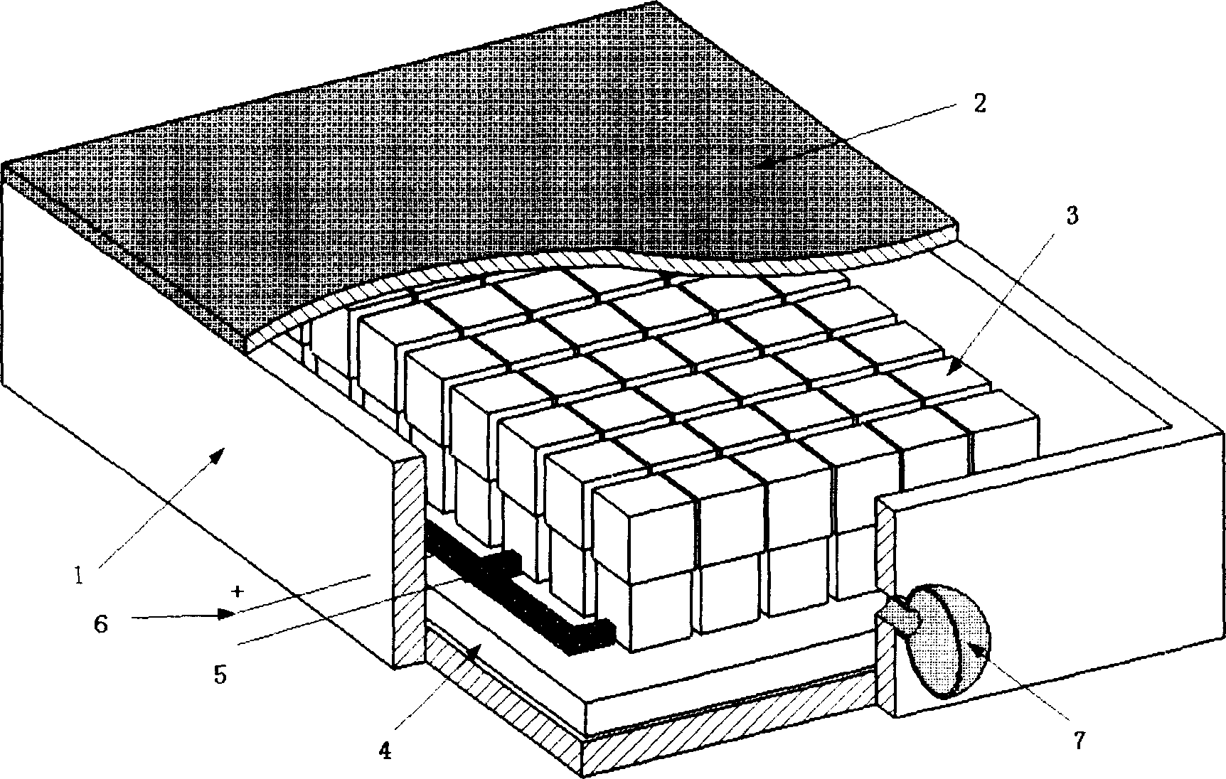
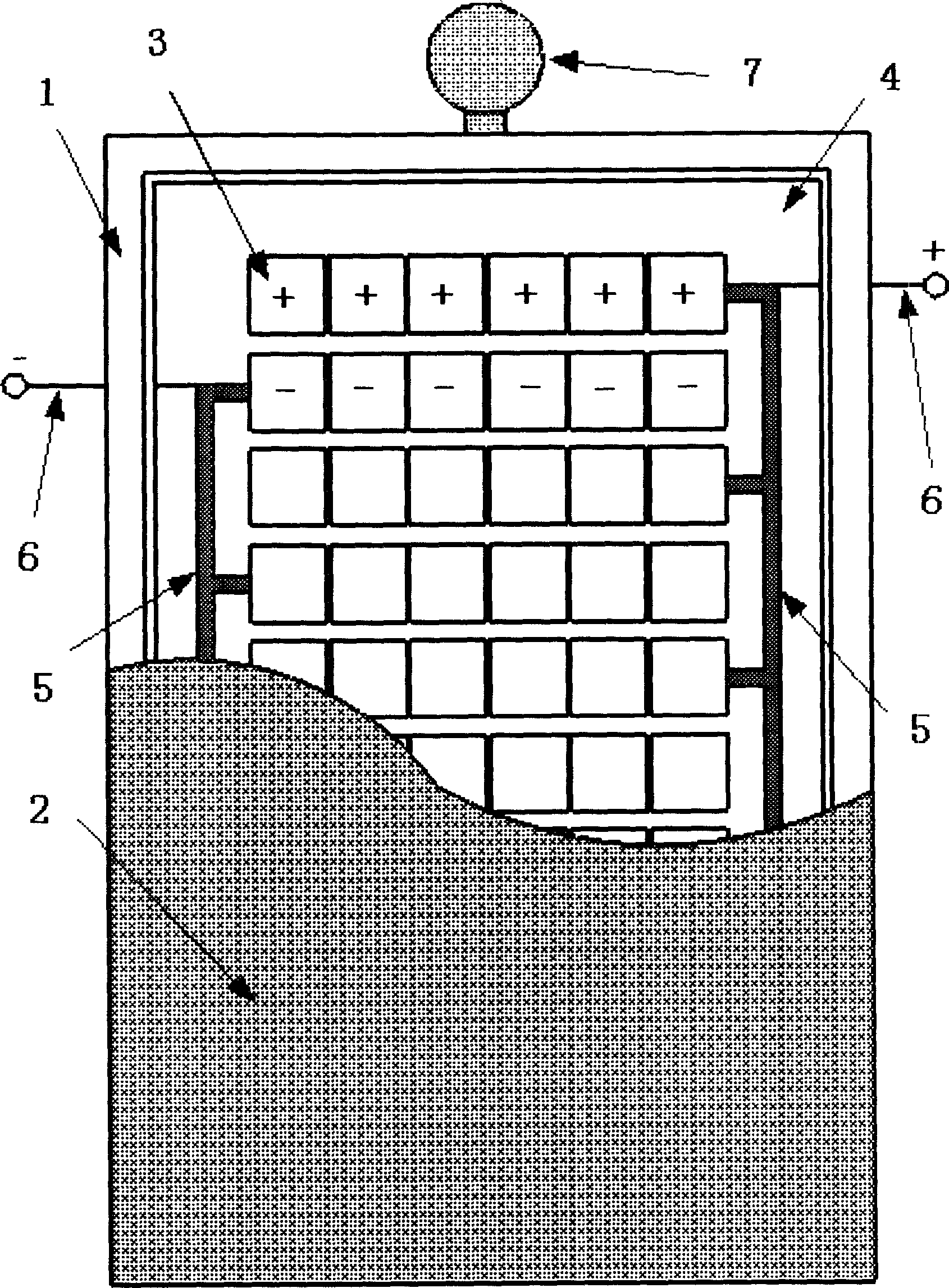
[0013] see figure 1 and figure 2 1 is a rectangular container (such as 50mm * 30mm * 5mm) with an upper opening, and 2 is a high elastic film (such as a rubber film) covering the upper opening. 3 is ten rows of electrodes arranged in the container, with a spacing of 0.5mm; all electrodes are fixed on an insulating plate 4, and the insulating plate (such as a plastic plate) is fixed on the cavity of the container by bonding. bottom. The high elastic film 2 is bonded on the periphery of the container 1 and the upper end surface of the electrode by superglue. The first row of electrodes is positive and the second row is negative (or vice versa, that is, the first row of electrodes is negative and the second row is positive), and so on, the positive and negative alternate. After the individual electrodes in each row are connected in series, the first, third, fifth, seventh, and ninth rows (singular rows) are respectively connected to the conductive strip 5, and after parallel ...


PUM


Abstract

The invention relates to a method for producing robot, mechanical arm or mechanical clamp, and the application technique of current flowing deformation liquid. It comprises a finger and a flexible surface formed by flexible film. Wherein, the finger comprises a container with a open while expansion flexible electrodes in array are arranged in the chamber of said container; said flexible surface is fixed on the open of container and connected to the upper surface of each electrode; the polarities of the electrodes in one group are same while they are parallel; the electrodes of nearby groups have reverse polarities; the groups in same polarity are paralleled and connected to a outer circuit via lead; the space between each group is filled by current flowing deformation liquid. The invention can realize the deformation of current flowing deformation and the flowing property via regulating the strength of electric field, therefore, it can non-stepped adjust the rigidity of flexible surface to apply the clamped matters in different rigidities and shapes and confirm the clamping stability, without hurting clamped matters.

Description

Technical field: [0001] The invention relates to the manufacturing technology of robots, manipulators or mechanical fixtures, and also relates to the application technical field of electrorheological fluid. Background technique [0002] In the robotics and aerospace industries, it is often necessary to use compliant surfaces with controlled stiffness. When it is necessary to hold an object with an irregular shape, such as the fixture used in industry and the manipulator used by the robot, when it needs to locate and grasp a specific object, in order to reduce the contact stress, increase the contact area and increase the friction force, the contact surface is required Have a certain flexibility. This can prevent the clamped object from being pinched and improve the stability of the clamping. The methods currently used mainly include the use of elastic materials, such as rubber and high molecular polymers, to cover the contact surface and the use of special mechanical struc...

Claims


Application Information

Patent Timeline
Patent Type & Authority Applications(China)
IPC IPC(8): B25J15/08
Inventor 龚兴龙钱林俊张先舟张培强
Owner UNIV OF SCI & TECH OF CHINA
Why Eureka
Try Eureka